How can I make a scanner led light using 1,25 V X 0.054 ma (VIMUN SC - 3012) ?

Thread Starter

sciencetoolbar

Joined Apr 9, 2017
87
I just meant the same light level used in your typical example videos.

Well, I read your meter the same as you have reported: ~1.3V open circuit and ~54µA on the 2mA scale. What do you see if you switch the DC current selector on your meter to a higher scale, such as the 20mA or 200mA scales?
I understand now, I will be at the office on monday, to have the same conditions. I will do that, no problem (+ 1 movie )
st
 

Thread Starter

sciencetoolbar

Joined Apr 9, 2017
87
What happens when you put your second coil close to the solar powered one? Without the sphere in the mix.

What is up with the"string"? The one you drape over the upper support for the sphere?
I understand now ! I didn.t try it but I will test it.
Ref to the other question HP already answer . Thx HP
 

Thread Starter

sciencetoolbar

Joined Apr 9, 2017
87
@sciencetoolbar

As a point of curiosity (Re: spectra) might I inquire as to your light source (e.g. linear florescents, Hg/metal-halide HIDs, LEDs, halogen-filled incandescents, etc...)? --- Based upon the reflections apparent in your videos such could be any of the above or indeed sunlight (via skylights/windows)...:confused:

Very best regards
HP:)
There is now sunlight in that room ( no skylight, no windows) , only artificial light provided by : http://www.lighting.philips.com/mai...tl-d-standard-colours/928048005453_EU/product
thx st
 
Last edited:

Thread Starter

sciencetoolbar

Joined Apr 9, 2017
87
As I promised : the new movie with the measurements ( current and voltage) for Vimun Sc 3012-2a mini solar panel.
I wish to asure you that the title of the topic is correct.
Thx,
ST
 
Last edited:
As I promised : the new movie with the measurements ( current and voltage) for Vimun Sc 3012-2a mini solar panel.
I wish to asure you that the title of the topic is correct.
Thx,
ST
Based upon your videos and descriptions I'm now convinced you've managed to assemble an electric motor operable by less than 100μW (glory be to 'magnetic bearings' and, I daresay, a quality approaching infinite patience!) sincerely bravo!:cool: -- I'd never have credited it:)! -- That said, it remains my strongly held opinion that electro-mechanical conversion is insufficiently efficient for application to your proposed project... But hey! A 'toy' featuring a visibly moving part (i.e. the rotor) is certain to prove more intriguing in the eyes of most than a flashing LED! -- To that end, the requirement of manual intervention (i.e. supplying starting torque) might be counted as a 'plus'!:)

Very best regards
HP
 

Thread Starter

sciencetoolbar

Joined Apr 9, 2017
87
Based upon your videos and descriptions I'm now convinced you've managed to assemble an electric motor operable by less than 100μW (glory be to 'magnetic bearings' and, I daresay, a quality approaching infinite patience!) sincerely bravo!:cool: -- I'd never have credited it:)! -- That said, it remains my strongly held opinion that electro-mechanical conversion is insufficiently efficient for application to your proposed project... But hey! A 'toy' featuring a visibly moving part (i.e. the rotor) is certain to prove more intriguing in the eyes of most than a flashing LED! -- To that end, the requirement of manual intervention (i.e. supplying starting torque) might be counted as a 'plus'!:)

Very best regards
HP
thx HP I apreciate! I wish a led which is not blinking - Dc current - I am thinking to add some small neo magnets on the rotor. It will be complicated but this is the reason I am here
 

shortbus

Joined Sep 30, 2009
10,049
thx HP I apreciate! I wish a led which is not blinking - Dc current - I am thinking to add some small neo magnets on the rotor. It will be complicated but this is the reason I am here
I thought you said the sphere/rotor was a magnet? Just having a rotating magnet(s) without a commutator will always give AC output. The difference between a DC generator and an AC alternator is the DC one has a commutator. The alternator needs a diode bridge to make DC from its AC output.
 

Thread Starter

sciencetoolbar

Joined Apr 9, 2017
87
I thought you said the sphere/rotor was a magnet? Just having a rotating magnet(s) without a commutator will always give AC output. The difference between a DC generator and an AC alternator is the DC one has a commutator. The alternator needs a diode bridge to make DC from its AC output.
Hello SB!
Yes , the rotor ia a magnetic sphere 19 mm diameter, I am thinking to add some weight on it , max 150 g, (neo magnets on the rotor or a system containing neo magnets ) + coil + bridge to obtain Dc current . For the moment I am using a 16V 1000uF capacitor on the chip board. Do you think a larger capacitor will help (to obtain more speed..) ?
thx
st
 
Last edited:

shortbus

Joined Sep 30, 2009
10,049
Don't know about the cap. But do know adding more magnetism to the sphere will cause more resistance to making it turn Due to the higher magnetism trying to charge the second coil. The same goes for adding a iron core in the first coil, it takes more to power to magnetize the core. There are no free lunches in this stuff.

Did you ever do the test with both coils close to each other and no sphere?
 

Thread Starter

sciencetoolbar

Joined Apr 9, 2017
87
Don't know about the cap. But do know adding more magnetism to the sphere will cause more resistance to making it turn Due to the higher magnetism trying to charge the second coil. The same goes for adding a iron core in the first coil, it takes more to power to magnetize the core. There are no free lunches in this stuff.

Did you ever do the test with both coils close to each other and no sphere?
Yes, I tested, there is nothing there ( refering to voltage and current ).
I am testing diferent coils now and /i hope that someone can help me with the capacitor.
thx st
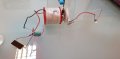
low consumption motor.jpg
 
/i hope that someone can help me with the capacitor.
thx st
Inasmuch as you insist upon high permittivity capacitors (and, perforce, as a practical matter, electrolytics) please be advised that dry tantalum compares quite favorably with 'Aluminum' from stability and dissipation/'ESR' standpoints...

Best regards
HP
 
Last edited:
@sciencetoolbar

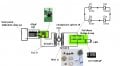
A further request -- Please post a complete schematic of the driver circuit -- including identification of (or circuitry contained within) the COB -- Should said IC be unmarked or otherwise unidentifiable, please advise us as to the manufacturer of the PCB such that we may seek documentation for same:)

Best regards
HP
 
Last edited:

Thread Starter

sciencetoolbar

Joined Apr 9, 2017
87
@sciencetoolbar

A further request -- Please post a complete schematic of the driver circuit -- including identification of (or circuitry contained within) the COB -- Should said IC be unmarked or otherwise unidentifiable, please advise us as to the manufacturer of the PCB such that we may seek documentation for same:)

Best regards
HP
Hello HP for the initial one which Tony was kind to help me with the schematics or for the" latest model" ?
 
I don't see that being a help. The core will take much more magnetizing current from the already small solar panel.
Whereas magnetic coupling via an 'air core' (μ≈μ0) is insignificant (perhaps unmeasurable via standard instruments) at the rather low fundamental frequencies ( < 100 Hz) consistent with the phenomena presented in the videos -- Hence my suggested re-evaluation of mutual-inductance via a high permeability (but by no means practical) core:)

The core will take much more magnetizing current from the already small solar panel.
Agreed! hysteresis (and, come to that, eddy current) losses will be significant! -- Even so, said experiment may provide data from which the performance of a 'properly conceived' transformer might be extrapolated...

@sciencetoolbar
Should you wish to examine the 'possibilities' with an appropriate core from the 'get go' - please substitute the bolt (referenced in post #152) with a 'ferrite rod' (Note that 'material 77' strikes an excellent 'balance' between high permeability and (reasonably) high volume resistivity:) --- Note also that increased core permeability may well enable further increases in efficiency via exploitation of the greatly reduced turns-to-inductance relationship afforded thereby:)

Hello HP for the initial one which Tony was kind to help me with the schematics or for the" latest model" ?
Please provide a link:confused: -- The schematics apparent on this thread treat the COB as a 'black box':confused: --- While it is clearly some manner of multivibrator followed by a 'saturable' semiconductor output stage -- one fairly pines for a glimpse of the 'master plan', as it were:cool:

Best regards
HP
 
Last edited:
Top