Facebook
 Google
 GitHub
 Linkedin
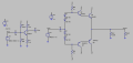
I made a CE amplifier as the first stage with a gain of around 10 with Rc = 10K, Re = 910, and biased the base voltage using Rb1 = 270K and Rb2 = 30K (to GND).
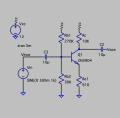
I want to preserve my signal of -5V to 5V with a gain of 10 at the collector output of the CE amplifier and I read that I have to use a voltage follower using a CC configuration however because of the high output impedance of my CE amp at 10K, I can hardly get any output signal. I don't know how to match the impedance of my CE and CC amplifier to preserve my signal of 10Vpp. I want my CC amplifier to be a voltage follower that also outputs around the same 10Vpp signal as my CE amplifier. I also have trouble choosing Re for the CC configuration. Choosing Vcc = 12V, I assumed that Vre~0.5Vcc and Icq = Ieq = 0.2A such that Vre = 6V and Re = 30 so then I used a voltage divider to bias the base at around this same voltage.
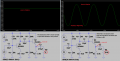
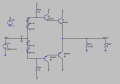
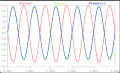
I also tried using a push-pull configuration as suggested by YouTube videos for the second stage and it works in preserving a raw 10Vpp signal without source impedance through it but as soon as I connect my two transistor stages, the output voltage drops significantly because of I presume the CE output impedance. I will attach my circuit here.
I want to preserve my signal of -5V to 5V with a gain of 10 at the collector output of the CE amplifier and I read that I have to use a voltage follower using a CC configuration however because of the high output impedance of my CE amp at 10K, I can hardly get any output signal. I don't know how to match the impedance of my CE and CC amplifier to preserve my signal of 10Vpp. I want my CC amplifier to be a voltage follower that also outputs around the same 10Vpp signal as my CE amplifier. I also have trouble choosing Re for the CC configuration. Choosing Vcc = 12V, I assumed that Vre~0.5Vcc and Icq = Ieq = 0.2A such that Vre = 6V and Re = 30 so then I used a voltage divider to bias the base at around this same voltage.
I also tried using a push-pull configuration as suggested by YouTube videos for the second stage and it works in preserving a raw 10Vpp signal without source impedance through it but as soon as I connect my two transistor stages, the output voltage drops significantly because of I presume the CE output impedance. I will attach my circuit here.
Attachments
-
3.1 KB Views: 4
-
 208.2 KB Views: 10
 -
 71.6 KB Views: 11
 -
 148 KB Views: 11
 -
 126.6 KB Views: 9