How can I convert potentiometer 555 pwm replacing it with hall sensor throttle

Thread Starter

ebenmoore

Joined Jul 24, 2017
3
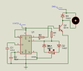
I have a problem in using Hall sensor throttle in 555 pwm. I want to replace the potentiometer with hall sensor but I can't.
Pls, I will need an assistant on it. Thanks.


Mods Edit:
Please don't post your email on forum, it could bring the spammer to our forum and your email account.
 

Thread Starter

ebenmoore

Joined Jul 24, 2017
3

Attachments

Sensacell

Joined Jun 19, 2012
3,445
This circuit is not an easy design to modify for voltage control- assuming the throttle you bought outputs an analog voltage.
Better to use a triangle wave generator driving a comparator, then the PWM control can be a voltage.

By scaling the triangle wave correctly, you can make the PWM vary from 0 to 100 % very easily.
 

Alec_t

Joined Sep 17, 2013
14,313
I agree with Sensacell. From my reading of the spec for that throttle it requires a 5V supply and outputs an analogue voltage in the ~1V-~4V range. Ditch the 555 circuit, unless a pulse which varies both in width and frequency is acceptable, in which case a modification of the 555 circuit might be possible.
 

crutschow

Joined Mar 14, 2008
34,428
Here's a PWM circuit using LM339 or LM393 comparators with a 1V-4V input control range that should do what you want:
It goes from 0% to 100% duty-cycle
The value of R3 determines the sensitivity, a smaller value increases sensitivity and a larger value reduces sensitivity.

upload_2017-7-24_16-56-4.png
 

Attachments

Last edited:

EM Fields

Joined Jun 8, 2016
583
Here is the link to the Hall sensor throttle i bought on aliexpress.
https://www.aliexpress.com/item/Uni...32633911535.html?spm=a2g0s.9042311.0.0.Khf1NX

So, i will like to replace the potentiometer with this hall sensor. below is the cct diagram of the 555 PWM i have.
Using a 5 volt supply, the device you ordered outputs a voltage somewhere between 1 and 4 VDC depending on the position of the handgrip, while RV1, in the drawing you referenced, is effectively two pots used to generate different charge and discharge time constants in concert with C2.
Consequently, the bottom line is: " There's no simple way to substitute the Hall sensor for RV1."
 
Top