How can I connect these two circuits using a D flip-flop?

Thread Starter

pinkoryx

Joined Dec 11, 2017
47
Hello,
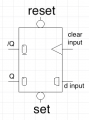
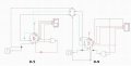
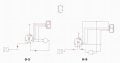
i have made 2 circuits and would like to connect them using a D flipflop so that the first (0-5) counter doesn't 'count up' until the second (0-9) circuit resets


How may I go about doing so?


PS. - the program I'm using is CEDAR Logic Simulator
 

Attachments

WBahn

Joined Mar 31, 2012
30,062
What signal in the first circuit tells you when the second circuit should start doing something?

What signal in the second circuit tells it to start doing something?

How could you use the flip flop to capture that the first signal has told you that the second signal should start doing something?

How could you use the flip flop to tell the second circuit to do something once it has captured the event from the first circuit?

These are the kinds of questions you need to start asking yourself about the problem you are trying to solve.
 

Thread Starter

pinkoryx

Joined Dec 11, 2017
47
Hmm... I guess the 0-9 counter would be on connected to the "input" ports on the flipflop, am I correct?

What signal in the first circuit tells you when the second circuit should start doing something?

What signal in the second circuit tells it to start doing something?

How could you use the flip flop to capture that the first signal has told you that the second signal should start doing something?

How could you use the flip flop to tell the second circuit to do something once it has captured the event from the first circuit?

These are the kinds of questions you need to start asking yourself about the problem you are trying to solve.
 

WBahn

Joined Mar 31, 2012
30,062
Hmm... I guess the 0-9 counter would be on connected to the "input" ports on the flipflop, am I correct?
Connected how? Just saying that the counter needs to connect to the flip flop buys you nothing.

First things first. Do you understand the basics of what a flip flop does and what you need to do with each input pin to get it to do what it does?

Then answer the very specific questions that I asked you.

How can you possibly figure out how to connect the counter to the flip flop until you can clearly state how you can tell from the counter's outputs what you need to know?
 

Thread Starter

pinkoryx

Joined Dec 11, 2017
47
Connected how? Just saying that the counter needs to connect to the flip flop buys you nothing.

First things first. Do you understand the basics of what a flip flop does and what you need to do with each input pin to get it to do what it does?
Unfortunately, nope
 

Thread Starter

pinkoryx

Joined Dec 11, 2017
47
What signal in the first circuit tells you when the second circuit should start doing something?
When power is on


What signal in the second circuit tells it to start doing something?
When it resets

How could you use the flip flop to capture that the first signal has told you that the second signal should start doing something?
How could you use the flip flop to tell the second circuit to do something once it has captured the event from the first circuit?
clueless
 

WBahn

Joined Mar 31, 2012
30,062
So exactly what is the second circuit supposed to start doing when the power is on to the first circuit? Doesn't it seem strange that the counter in the first circuit doesn't seem to matter? Only the power?
 

Thread Starter

pinkoryx

Joined Dec 11, 2017
47
So exactly what is the second circuit supposed to start doing when the power is on to the first circuit? Doesn't it seem strange that the counter in the first circuit doesn't seem to matter? Only the power?
It should send a signal to the first (0-5) counter to count one digit up

Of course it matters... when it counts up it should send a signal to the second counter to begin counting
 

Thread Starter

pinkoryx

Joined Dec 11, 2017
47
Because I want the first counter to count up ONLY when the second one has finished, I connected the output of R on the second counter’s register with the set input on the flipflop
Then connected the ^-shaped inputs on the register and flipflop, and the reset output with the ^-shaped input on the first (0-5) register (screenshots attached).

It’s not working though, what have I done wrong?
 

Attachments

dl324

Joined Mar 30, 2015
16,922
It’s not working though, what have I done wrong?
What is it doing wrong?

Stop and think for a moment how you want the two counters to interact. Don't you want to have the least significant digit (LSD) increment the most significant digit (MSD) when it rolls over to zero?

What are you trying to accomplish by connecting two inputs together when there is no driver?
upload_2017-12-16_9-44-55.png

What are you hoping to do by shorting the Q' output of the flip flop to ground? And by having the Q output connected to an input that's never enabled?
upload_2017-12-16_9-40-37.png

If you expect others to attempt to read your schematic, you should make an effort to draw one that's easier to read. You have unnecessary wire jogs. You should never have overlapping wires (unless they're a bus).
 

Thread Starter

pinkoryx

Joined Dec 11, 2017
47
The thing is I am asked to do this assignment (and it's worth a lot of my final grade) and have 0 knowledge about D flip flops, what they do, how they work, registers (and their connections), which is why I'm here. I have done research on the internet and it was of no help. Also,I am not given enough information on these topics in my curriculum to begin with which is why i'm lost (I didn't even know the thing I'm working on is called a mod 60 counter until you mentioned it)

sorry if my circuit looks like a headache i'm a total newbie who just needs some guidance
 

dl324

Joined Mar 30, 2015
16,922
Are you required to use a D flip flop in the circuit? It isn't required.

Since you're lost and this assignment is a large portion of your grade, it's more important for you to learn than it is to get the circuit right or complete.

If you're not given clear instructions, you should ask for clarification. If you ask clarification and they can't give it, you should consider finding a better school.
 

Thread Starter

pinkoryx

Joined Dec 11, 2017
47
Yeah im required to use a D flip flop and yeah you're probably right but I don't think I'm given enough information to learn it. I go to a public college, unfortunately decent education is pricey and my family can't afford it

cheers
 

dl324

Joined Mar 30, 2015
16,922
There are many problems with public schools, but it's still possible to get a decent education from the vast majority of them. Students also need to ask questions and put in sufficient effort to learn the material.

In your case, I think the problem is the instructor; as evidenced by the three typos in the 3rd page of instructions where 10th was used in place of 10's. There's no excuse for that. You should also be being taught how to draw readable schematics.

A flip flop isn't required to connect the two counter circuits. So I'll ask again. Are you certain you're required to use a D flip flop, or was it just a suggestion?
 

dl324

Joined Mar 30, 2015
16,922
I can try to guide you through how to do it without, and then with, a D FF. You can decide which you want to turn in. Personally, I'd take points for an unnecessarily complicated solution. I'd also take points for sloppy work.

Since you want the second counter (10's digit) to be clocked once every 10th clock, does your 0-9 counter have such a signal available?
 

dl324

Joined Mar 30, 2015
16,922
Let's not guess.

Here are the inputs and relevant outputs from the first counter stage:
upload_2017-12-16_14-51-59.png

I got this using the oscope feature in Cedar Logic.

clk1 is the clock to the counter. A, B, C, and D are the counter outputs, with D being the Most Significant Bit (MSB). R1 is the signal going to reset on the first counter.

With your choice of these signals, which signal could be used to increment the second counter when the first rolls over from 9 to 0?
 

Thread Starter

pinkoryx

Joined Dec 11, 2017
47
Just so we're on the same page, the first counter counts from 0-5 and the second counts from 0-9, right?

Since R1 is responsible for resetting the counter, it would make sense that this signal is used to trigger the 0-5 counter to increment
 
Top