Homework Help

Thread Starter

thisonedude

Joined Apr 20, 2014
52
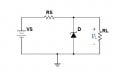
So I am currently working on some homework and cam across this problem. The circuit is attached. The problem asks us to determine the load voltage Vl for RL equal to:
i. Open Circuit
ii. 10kOhm
iii. 1KOhm
iv. 100Ohm

I'm stuck because I don't know how to approach this problem. Do i have to find the thevenin equivalent for each? How do I do that with the Zener diode? Any help would be much appreciated!
 

Attachments

Thread Starter

thisonedude

Joined Apr 20, 2014
52
Oh Yes sorry.:
Rs = 1KOhm
VS = 15V
D: Ideal Zener diode with reverse breakdown voltage VZ = 5.6V

For the open circuit, would i just have to do something like KVL to find that voltage drop across D?
 

WBahn

Joined Mar 31, 2012
33,186
Generally you treat the non-linear element as the load and find the Thevenin or Norton equivalent for the rest of the circuit. That will let you find the voltage across the diode very easily and since this is also the voltage across the load, you are done.
 

Thread Starter

thisonedude

Joined Apr 20, 2014
52
Okay so then i were to get the equivalent i would have of the open circuit problem:
the current source would be 15A and the Resistor 1k? and the i would the diode and all of these would be in parallel?
 

WBahn

Joined Mar 31, 2012
33,186
Okay so then i were to get the equivalent i would have of the open circuit problem:
the current source would be 15A and the Resistor 1k? and the i would the diode and all of these would be in parallel?
Yes, but for this problem using a Thevenin equivalent will make the answer scream out at you.
 

WBahn

Joined Mar 31, 2012
33,186
Isn't it already in Thevenin? Isn't it just the 15V and the 1K resistor?
You said a 15A source and a 1kΩ resistor and the diode, all in parallel. That is NOT a Thevenin circuit.

It would help a LOT if you would provide a circuit diagram. It can be something scribbled in Paint.
 

WBahn

Joined Mar 31, 2012
33,186
Rs and Rl are not in series (as seen from where the diode is connected).

Don't try to shortcut things.

First, draw the circuit with the diode removed and, instead, with the port terminals in it's place with the Vout clearly labeled (including polarity). Do this for the generic case (i.e., any load resistance) so that you don't have to do it four times.

Then calculated Vout -- this is the Thevenin voltage.

Now turn off the independent sources and redraw the circuit that results.

Now calculate the resistance between the port terminals. That is the equivalent resistance.
 

Thread Starter

thisonedude

Joined Apr 20, 2014
52
Sorry if i may seem dumb. I'm just learning this and I'm trying to understand it. Let me see if i understand. These are the steps I did:

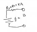
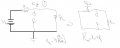
First: I removed the diode and left two terminals in it's place: Fig1:

Second: I did the voltage divider to find the voltage across Rl = Vout

Third, I shorted the battery and found Rth: Fig 2

Finally, i redrew the cricuit with the Vth and Rth? But do i replace the diode? Fig 3
 

Attachments

WBahn

Joined Mar 31, 2012
33,186
Sorry if i may seem dumb. I'm just learning this and I'm trying to understand it. Let me see if i understand. These are the steps I did:

First: I removed the diode and left two terminals in it's place: Fig1:

Second: I did the voltage divider to find the voltage across Rl = Vout

Third, I shorted the battery and found Rth: Fig 2

Finally, i redrew the cricuit with the Vth and Rth? But do i replace the diode? Fig 3
Look at your Figure 2. Those two resistors are NOT in series. In order to be in series, current that goes from one terminal through one of the resistors would have to then flow through the other resistor in order to reach the other terminal. That's not the case here, is it. Whatever voltage is applied to the port terminals appears across each resistor, right? That describes resistors that are connect in _____?
 

WBahn

Joined Mar 31, 2012
33,186
They are in parallel!
So the Rth would be RsRl/(Rs+Rl), and the Thevinen circuit would like fig 3.
Yes!

So now put your diode back in. Given the Thevenin voltage and the diode's Zener voltage, can you tell immediately whether or not the diode is conducting current and, if it is, how much current?

Once you know the diode voltage and current, you can then go back to the original circuit and use that information as "knowns" and start solving for the rest.
 
Top