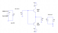
Homework Help.... Design of transformer coupled Push Pull (Class-B)

Ian0

Joined Aug 7, 2020
9,667
I was referring to your circuit in Post #15.

There's one thing that I'm curious about - it seems to have a transformer with a variable tap. That would theoretically set the balance between the two devices; whereas at first glance I expected it to be for setting the bias, but the bias is fixed by R1 and R2.
A whole load of similar circuits are here
http://www.introni.it/pdf/Mullard - Reference Manual of Transistor Circuits 1960.pdf
pdf page 162, real page 148.
Yours must be a little later as all the germanium ones would be pnp.
 

Audioguru again

Joined Oct 21, 2019
6,672
The original amplifier with complementary emitter-followers produces much less distortion than the amplifier with common-emitter transistors (when both amplifiers are properly biased in class-AB) because common-emitter transistors produce a lot more voltage gain and a lot more distortion than emitter-followers.

I see nothing that makes a transformer-coupled amplifier less efficient than a direct-coupled amplifier except the tiny amount of heating in the resistances of the transformers that wastes a small amount of power.
The main difference is that a transformer might cost more than a few direct-coupled amplifiers and the transformers reduce the bandwidth.
 

Ian0

Joined Aug 7, 2020
9,667
I see nothing that makes a transformer-coupled amplifier less efficient than a direct-coupled amplifier except the tiny amount of heating in the resistances of the transformers that wastes a small amount of power.
Exactly: that's the question I was encouraging the TS to answer for himself. Transformers, even audio transformers with extended low-frequency bandwidth are relatively efficent.

And I also forgot that the original spec was for Class B!
 

Audioguru again

Joined Oct 21, 2019
6,672
Probably he meant to specify AD161/AD162
What a coincidence. My first job was as a technician on the Philips car radios production line. The latest one used AD161 and AD162 germanium complementary output transistors. It was spec'd at 4W into 8 ohms so instead of using bridged amplifiers, it used little output transformers to step-up the output signal voltage.
In those days, when a product costed more then the profit was more.
 

Ian0

Joined Aug 7, 2020
9,667
Unusual for being a complementary pair. Germanium NPN power transistors are as rare as hens' teeth.
First amp I every "built" when I was about 16 (I assembled it out of modules) had 10W modules with AD161/2 output stages.
 

Thread Starter

asbjc

Joined Oct 30, 2020
32
Hi, I tried B class Amplifier with and without transformer coupling.

Results:

With transformer coupling at input, output:

Power output : 4W

Power drawn from each DC Source : 4.9W

Efficiency: 41%


--------------------------------------------------------
Without transformer coupling:

Power output : 4W

Power drawn from each DC Source : 6.3W

Efficiency: 32%


Why is that ?
 

Attachments

Thread Starter

asbjc

Joined Oct 30, 2020
32
Hi a
Checked your Fi5, severe cross over distortion, try a 0.68v input signal ie: 10%.
E
Yes, but i think it is intend to get a crossover distorted signal in output, as it is class-B.

The issue is understanding thi Class B-amplifier efficiency in simulator.
It gets less without transformer. & gets more with transformer coupling.
 
Top