Hold push button, timer, then activate relay.

Thread Starter

IntempoDK

Joined Dec 29, 2016
9
Hi,

Im just a electrician, so i would really like some help on this.

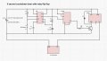
I have image attached, what i need is a plan and components to make this work, when i hold down the pushbutton for lets say 5 seconds, then the relay switches from NC to NO, then release, if i hold down again 5 seconds, relay switches back from NO to NC.

I have no clue what components to get and put together print wise, it doesnt sound like its hard to do if you know what your doing but im not, so i hope some of you here could have an idea about it :)

It should be as small as possible, so no big components if possible, but hope no SMD components, as i dont have that small fingers :p.

Thanks.
 

Attachments

dl324

Joined Mar 30, 2015
16,845
Welcome to AAC!

It sounds like you want an alternate action switch. If you don't really want to have to hold the button down for 5 seconds before it switches a mechanical alternate action switch would work.
 

Thread Starter

IntempoDK

Joined Dec 29, 2016
9
Thank you.
It must be that i hold down the button for 5 seconds to turn on, and again to turn off.
If release before time, it should do nothing, if i hold down 5 seconds, at 5th second, it switches state.

Like: Hold down button > timer starts from 5.0 -> goes to 0.0 -> switch state from NC to NO.
And of course other way around if i hold down 5 seconds again :)
If release before time, lets say 3 seconds in, it returns to 5.0 and wait push hold again.
 

Thread Starter

IntempoDK

Joined Dec 29, 2016
9
Of course i did a bit of research also :) just dont come rushing in asking.

Would i be wrong thinking i need a 555, somehow set to 5 seconds, downstate button puts 5v+ on trigger and where ever the + is on the 555 (so when i release i cut all power to the 555 chip and it stops), but after 5 seconds if i hold it down that long it sends a pulse out of (3) output into the relay trigger in, and it switches relay?
I would really just need help on what to put to make the 555 countdown about 5 seconds, and an idea if it would work like that?
 

dl324

Joined Mar 30, 2015
16,845
You could make a 5 second one shot with a 555 timer and use the switch position and the timer output to control a toggle flip flop.

What state do you require when power is first applied?
 

dannyf

Joined Sep 13, 2015
2,197
fairly easy to do with a mcu, or plc / ladder logic.

for discrete logic, it would be a monostable timer where the switch controls the charge / discharge path, feeding into a flip/flop.
 

dl324

Joined Mar 30, 2015
16,845
after 5 seconds, it sends a pulse out of (3) output into the relay trigger in, and it switches relay?
Configuring the timer as a delay might be easier at that. I was wondering how to deal with the propagation delay if the timer was used as a one shot...
 

crutschow

Joined Mar 14, 2008
34,282
Below is a circuit that should do what you want.
It uses one CMOS Schmitt trigger NAND gate chip, one CMOS flip-flop, one N-MOSFET, two diodes, and a few passive parts.
The P-MOSFET can be just about any logic-level type [Rds(on) is rated at a Vgs of 5V or less in the data sheet].

The LTspice simulations shows that a PB time of 4s (first pulse) does not cause a change of the relay state but a press of more than 5s does.

If you need to have it come up in a particular state at power-on, an added resistor and capacitor to the flip-flop PREset or CLR input will insure that.

Note that the power and ground to the two CMOS chips aren't shown, which must be connected.

It requires essentially no power when the relay is off.

upload_2016-12-29_16-0-39.png
 

Attachments

Last edited:

dannyf

Joined Sep 13, 2015
2,197
here is a ladder logic example: the timer is set to trigger if pressed continuously for 120ms (user configurable):

delay switch.PNG

the coding is easy in ladder logic:
delay switch - ladderlogic.PNG

tough to beat that: two lines only and gui-based - no language to learn.
 

GopherT

Joined Nov 23, 2012
8,009
Connect a push button (momentary) stdp as follows.

When the switch is not pressed, it will be connected to the low value resistor and ground (low value resistor is needed so you don't get a spark and wear out the switch).

When the button is pressed, the capacitor will charge (through the high value resistor) until the Flip Flop triggers and sets the new state. Holding longer does nothing to the flip flop state.


Something like this...

Q1 and Q1 bar will alternate states with each button press.
image.png
 

crutschow

Joined Mar 14, 2008
34,282
Connect a push button (momentary) stdp as follows.

When the switch is not pressed, it will be connected to the low value resistor and ground (low value resistor is needed so you don't get a spark and wear out the switch).

When the button is pressed, the capacitor will charge (through the high value resistor) until the Flip Flop triggers and sets the new state. Holding longer does nothing to the flip flop state.

Something like this...

Q1 and Q1 bar will alternate states with each button press.
View attachment 117700
That may not work well in practice since most flip-flops have a minimum rise-time requirement for the clock input.
You likely need to add a Schmitt trigger, as I have in my circuit, to give a fast clock rise-time.
 
Last edited:

dannyf

Joined Sep 13, 2015
2,197
an alternate implementation on attiny:

delay_switch_attiny.PNG

tuned to about 110ms of steady press on the button (active high).

you cannot find anything simpler than that, :)

Code:
int main(void) {

    mcu_init();                                //reset the mcu
    IO_SET(SW_PORT, SW); IO_IN(SW_DDR, SW);    //sw as input, pull-up activated
    MTR_OFF(); IO_OUT(MTR_DDR, MTR);        //mtr as output, idles off
    mtr_state = 0;                            //reset motor state
    sw_cnt = 0;                            //reset motor cycle counter
    while(1) {
        if (SW_PRESSED()) {
            sw_cnt +=1;                    //increment motor cycle counter
            if (sw_cnt == SW_CYCLE) {        //cycle has been reached
                sw_cnt = 0;                //reset the cycle counter
                mtr_state += 1;                //increment motor state
                if (mtr_state & 0x01) MTR_ON(); else MTR_OFF();
            }
        } else sw_cnt = 0;                    //reset the count
        delay_ms(SW_DLY);                    //waste some time
    }

    return 0;
}
the same code would run on pretty much any mcu.
 

eetech00

Joined Jun 8, 2013
3,858
Below is a circuit that should do what you want.
It uses one CMOS Schmitt trigger NAND gate chip, one CMOS flip-flop, one N-MOSFET, two diodes, and a few passive parts.
The P-MOSFET can be just about any logic-level type [Rds(on) is rated at a Vgs of 5V or less in the data sheet].

The LTspice simulations shows that a PB time of 4s (first pulse) does not cause a change of the relay state but a press of more than 5s does.

If you need to have it come up in a particular state at power-on, an added resistor and capacitor to the flip-flop PREset or CLR input will insure that.

Note that the power and ground to the two CMOS chips aren't shown, which must be connected.

It requires essentially no power when the relay is off.

View attachment 117696
The CD4013B package has two flip flops. You could use the other FF as a pulse generator and eliminate the 4093B.
 

crutschow

Joined Mar 14, 2008
34,282
The CD4013B package has two flip flops. You could use the other FF as a pulse generator and eliminate the 4093B.
That's a good idea.
The old 4013 LTspice model I had didn't properly simulate the PRE and CLR logic to do that, but I now have the revised model that does, so here's my circuit that eliminates the 4093 and uses one of the FF's in the package as a non-inverting buffer to generate the needed fast-rise clock pulse for the second FF.
I also added a PREset signal on the right FF so the circuit powers up with the relay off.

upload_2016-12-29_23-44-8.png
 

Attachments

Last edited:

Thread Starter

IntempoDK

Joined Dec 29, 2016
9
Woo you guys do some serious stuff there, as i mentioned, im just an electrician, i dont have alot of equipment for this.

I was thinking more along the lines of this image, maybe i did wrong on it, just put together from some i found on the net, but i dont want to order the components if it wont work :p

I would like it to be as simple as possible, so others without a engineering grade can do it too, with simple items from electronics store if possible.

Thanks for the amazing info though :), but the simpler the better in this case, i have to be able to make it too :)

If i can do it without the 4027B then its even better, if any can look at this and tell me if its going to work or not, or what need to be changed, im all in for it, seems you guys know your stuff :)
 

Attachments

dl324

Joined Mar 30, 2015
16,845
If i can do it without the 4027B then its even better, if any can look at this and tell me if its going to work or not
It won't work. You have the timer configured as a one shot that will trigger as soon as the button is pressed. That will toggle the flip flop as soon as the button is pressed.

You have to let the timer time out and add some logic to implement your 5 second button hold requirement. Once you do that, you'll have more components than the last solution offered.
 

Tonyr1084

Joined Sep 24, 2015
7,852
So far I like Crutschow's second circuit. It's very simple and consists of just one IC (the CD4013), some resistors, a capacitor, a P-Channel MOSFET (they come in P-chan or N-chan types) and your relay and just a few other simple parts available almost anywhere. Using LTSpice just makes it look more complicated than it really is.
 

eetech00

Joined Jun 8, 2013
3,858
Woo you guys do some serious stuff there, as i mentioned, im just an electrician, i dont have alot of equipment for this.

I was thinking more along the lines of this image, maybe i did wrong on it, just put together from some i found on the net, but i dont want to order the components if it wont work :p

I would like it to be as simple as possible, so others without a engineering grade can do it too, with simple items from electronics store if possible.

Thanks for the amazing info though :), but the simpler the better in this case, i have to be able to make it too :)

If i can do it without the 4027B then its even better, if any can look at this and tell me if its going to work or not, or what need to be changed, im all in for it, seems you guys know your stuff :)
I recommend Crutschows circuit in post #15. Its simple and uses one chip...
 
Top