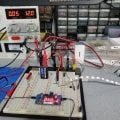
Im using a N-Channel High Voltage Mosfet IXTL2N450 to charge a High Voltage capacitor at 2kV between the Source and the ground however it is not working. Im trying to charge it on the high side so after I switch the mosfet off I can take a charge reading from the capacitor. Is this possible? What do i need to do this?
VDSS: 4500V
VGSS: +/-20V
VGS(th): Min 3.5v / Max 6.0v
VGS: 10v
RDS(on): 20Ω
VDSS: 4500V
VGSS: +/-20V
VGS(th): Min 3.5v / Max 6.0v
VGS: 10v
RDS(on): 20Ω
Last edited: