Facebook
 Google
 GitHub
 Linkedin
Hello,
I'm just first experimenting with MOSFET drivers. I bought a Microchip TC4432 High side driver http://ww1.microchip.com/downloads/en/DeviceDoc/21424d.pdf
I'm using an N-Channel MOSFET. The source is connected to a 12V battery positive lead. The Drain is connected to the solar panel positive lead. I can control the current flow (panel to battery) through the MOSFET with the TRC4432. Although I see a little current (400uA or so) getting through even when I have it turned off. Is that normal?
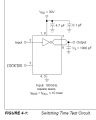
What confused me in the data sheet was the two output pins, source and sink output. They talk about tuning rise and fall times with different resistors on either pin. I just connected the source output (Pin 7) to the MOSFET gate directly (no series resistor). Should I have a pull-up resistor on that output pin? If so how do I determine the value of that?
They also say that supply input, VDD, should be bypassed to ground with a local ceramic capacitor. I left that off too. How should I determine the value of that cap?
I'm using the IRL3714Z http://parts.digikey.com/1/parts/1022752-mosfet-n-ch-20v-36a-220ab-irl3714z.html
I originally bought these for a low side application. They are rated at 20V VDss, most panels go no higher than 18V but I've seen them get up to 22V. So I should probably get a different part for this application?
Thanks in advance.
I'm just first experimenting with MOSFET drivers. I bought a Microchip TC4432 High side driver http://ww1.microchip.com/downloads/en/DeviceDoc/21424d.pdf
I'm using an N-Channel MOSFET. The source is connected to a 12V battery positive lead. The Drain is connected to the solar panel positive lead. I can control the current flow (panel to battery) through the MOSFET with the TRC4432. Although I see a little current (400uA or so) getting through even when I have it turned off. Is that normal?
What confused me in the data sheet was the two output pins, source and sink output. They talk about tuning rise and fall times with different resistors on either pin. I just connected the source output (Pin 7) to the MOSFET gate directly (no series resistor). Should I have a pull-up resistor on that output pin? If so how do I determine the value of that?
They also say that supply input, VDD, should be bypassed to ground with a local ceramic capacitor. I left that off too. How should I determine the value of that cap?
I'm using the IRL3714Z http://parts.digikey.com/1/parts/1022752-mosfet-n-ch-20v-36a-220ab-irl3714z.html
I originally bought these for a low side application. They are rated at 20V VDss, most panels go no higher than 18V but I've seen them get up to 22V. So I should probably get a different part for this application?
Thanks in advance.
Last edited:
 , although you don't actually hear it. A gate resistor would be required to reduce the ringing affect, especially if this a buck converter circuit. A scope would be really handy to see effects of different resistor values.