High power solenoid driver economizer circuit

MisterBill2

Joined Jan 23, 2018
27,888
The information on the operation is what is needed.
It seems that the 12 volt PWM signal can be applied thru a series diode the same instant that the operate command is issued, and no PWM current will flow until the 48 volt pulse ends. So there will be no need for sequential switching, the series diode will do that. That leaves the setting of the 48 volt pulse as the only thing that needs to be controlled. That can be switched off very shortly after the current peak starts to drop, which will be caused by the inductance increasing as the solenoid core moves.
 

Thread Starter

Backyard

Joined Oct 15, 2024
16
The information on the operation is what is needed.
It seems that the 12 volt PWM signal can be applied thru a series diode the same instant that the operate command is issued, and no PWM current will flow until the 48 volt pulse ends. So there will be no need for sequential switching, the series diode will do that. That leaves the setting of the 48 volt pulse as the only thing that needs to be controlled. That can be switched off very shortly after the current peak starts to drop, which will be caused by the inductance increasing as the solenoid core moves.
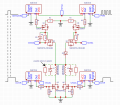
Well yes. In theory that is doable. But in practice I need a way to generate the PWM that has enough current capability. At least something around 5 amps. So that's where that half of the circuit comes into play

But the diode keeping the 48 volts from back feeding into the lower voltage PWM is the plan. In fact I don't think I even need to turn off the PWM at all. The 48 V will override the PWM and the solenoid will ultimately be controlled by the N channel fet on the lower part of the circuit
 

Thread Starter

Backyard

Joined Oct 15, 2024
16
M2 pulls up all the loads.
M2 is turned on by pulling the Gate below 48V. A 12V to 15V Zener is for safety.
Q3 makes a current. If the Base is at 5V and IN is at 5V there will be no current in Q3. R3 turns off M2.
If IN is at 0V there will be 4.3V in R5 which will result in about 8.5V across R3, turning on M2. The reason I chose to Gate drive this way is that if 48V drops in voltage there will be good Gate voltage on M2. I think 48V could drop to 12V and still work.
View attachment 333791
Ok, so I made some adjustments based on what's available to me and how the existing circuit signals are and based the design partially on yours. Mostly the gate resistor arrangement.

What do you think?
Solenoid Driver 2.png
Also, I'm not having much luck trying it out in a simulator as my experience with them is zero. Other then the dumbed down Falstad one which says it works but when I run them on the bench they don't. So not too reliable for my purpose.

If someone is skilled with simulators and is able to tell be how it runs that would be awesome
 

ronsimpson

Joined Oct 7, 2019
4,755
The solenoids measure about 120 uH and about 0.5 ohms if that helps at all
If the 0.5 ohms is true then 12V should get you 24 amps. Yes the inductance will help. Do you have information on the valve. data sheet. web address.
I was going to setup simulation for you.
 

Thread Starter

Backyard

Joined Oct 15, 2024
16
If the 0.5 ohms is true then 12V should get you 24 amps. Yes the inductance will help. Do you have information on the valve. data sheet. web address.
I was going to setup simulation for you.
No paperwork on the solenoid. I gathered that information from the solenoid itself. Measured it with an LCR meter. I don't know how accurate the 0.5 ohms is though as the meter doesn't have much resolution down below 1 ohm. But it was my understanding from scoping the running machine that it was close to 20 amps on the peak open and about 5 amps with PWM hold. The solenoid is about the size of four quarters stacked and is shielded
 

MisterBill2

Joined Jan 23, 2018
27,888
Those diodes across the solenoids will certainly slow the release times a bit. And they will certainly keep the current flowing when the PWM switches off.
You can gate the PWM signal, and control the SHORT 48 volts, so why then is there a third switching device included?? It is much simpler to control a signal than the power stream.
 

ronsimpson

Joined Oct 7, 2019
4,755
Do you have LT SPICE? It is free.

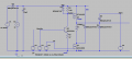
Click on the image to see a bigger picture.
Light blue trace is the 48V from a 48V 4A power supply with 33uF internal capacitance. Note how the voltage drops to 17V in 90uS. Then ramps back up at 4A.
Dark blue is the top of the solenoid. Jumps up to 48V drops back. Then PWM 12V at 50%.
Red is solenoid current.
1729211792331.png
As stated in many places the diode across the coil slows the turn off edge. I changed the diode to connect to 48V and now the current drops back to 0A in 1/20 of the time.

I attached the LT spice file. You will need a long explanation of how it works.
1729212281573.png
V3 is the PWM for now. Click on V5 to modify. For now the frequency is set by cycle time and the on time allows you to change the duty cycle.
V1, I1, D5 and C2 act like a 48V 4A supply.
V4 turns on/off the current.
V3 is set to 90uS on time. It jumps up the power from 12V to 48V.
Q2 is P-mos and because the 48V supply is not stable most Gate driver circuits will not work well. Q3 makes a special Gate driver.
RonS.
 

Attachments

Thread Starter

Backyard

Joined Oct 15, 2024
16
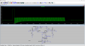
Alright, some updates. Using some design ideas from @ronsimpson's circuit I was able to make a version that looks to do what I need. Biggest issue I was running into was when I got the P mosfets to work on the positive side of the circuit, and the circuit seemed to be working, it would fail or do weird things when I added the N mosfet to the negative side of the circuit. I found I need to select the mosfets carefully for ones that have very low RDSon resistance. I am not sure if the mosfets I have here are going to actually work as I didn't look at their amp/wattage rating. But I can do that later after looking at what's available and crossing over the resistance rating to ones that can handle the current and voltage

Here is a screenshot and simulation file for LTSpice. The trace is the voltage across the solenoid. The current is around 30 amps or so at the peak and then drops down to less then 2 amps with the PWM that I have now. Might need to play with the frequency and duty cycle to keep the current high enough to keep the solenoid held. I think, based on the simulation it might be too low and drop out. But will need to test it to know for sure. If you want you can add or remove the snubber components to see how it effects the waveform, voltage and current.

Please let me know what you think and if there is anything you see that might improve the design
Solenoid Driver Circuit.png
 

Attachments

Top