 Facebook
 Google
 GitHub
 Linkedin
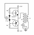
I want to drive current through a coil and capacitor at the resonant frequency. The circuit I am trying is attached. By using the tank circuit itself to create the oscillator, it is guaranteed to match the resonant frequency.
There is only one problem. It doesn't work. The resonant frequency is about 80kHz. I am using an Armstrong-type feedback. I ran a test 10V peak AC through the circuit to confirm that the feedback coil produced more than 10V. I biased the transistors so that there would not be a dead zone.
I know I am not understanding something, because it seems like it should work.
I would greatly appreciate it if somebody could enlighten me on how I messed up.
Attachments
-
 475.9 KB Views: 45


