Facebook
 Google
 GitHub
 Linkedin
Hi Everyone,
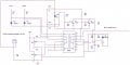
The Attached circuit diagram is used in inverter for High AC & Low AC tripping using LM339 configured as window comparator.
When the circuit test individually it works fine when the high AC 250 VAC detected & Low AC 180 VAC detected ,the output of the LM339 pin number 13 goes low after 20 second due to timer circuit.
But when the circuit integrates with inverter as shown in the block diagram & when the voltage increases or decreases with the limit ,
then PIN nimber 2 for high or pin number 1 for low goes low,but the pin number 13 does not goes low & when i check the voltage across C6
it shows 1 VDC which is below the reference limit which is 2.5VDC.
Kindly help me out.
Thanks.
Attachments
-
20 KB Views: 18