Hi, I made a project to write digital, but whenever I put a resistor on the display, doesn't work.

Thread Starter

Daniele Santos

Joined Jun 10, 2018
4
I'am tryng to use 7 270 ohms resistors on the display and 3 1k ohms on the dip, but doesn't work anymore, whitout the resistors it work.
 

Attachments

ebp

Joined Feb 8, 2018
2,332
I can't see enough detail in your schematic to tell what type of gates you are using.

How are you connecting the 1k resistors? Does the display work if you have the 270 ohm resistors but not the 1k resistors?
 

WBahn

Joined Mar 31, 2012
29,932
I'am tryng to use 7 270 ohms resistors on the display and 3 1k ohms on the dip, but doesn't work anymore, whitout the resistors it work.
Are you talking about it not working in simulation, or in a physically implemented circuit?

Where are you placing these resistors? "on the display" and "on the dip" doesn't tell us much?

If you are doing this in simulation, then what simulator?

If you are doing this in the real world, then what logic family? What 7-seg display? You also need pullup resistors?

Why 270 Ω? Why 1 kΩ? Why not larger or smaller?

Is this homework? Say, perhaps, displaying your student ID number?
 

absf

Joined Dec 29, 2010
1,968
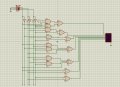
If after putting in the 270E resistors, the circuit doesn't work, then it could be due to the TTL poor current sourcing property to light up the LED with insufficient output current.

I changed all the OR gates to NOR gates and using common anode display and it worked with the resistors.

daniele cct.PNG
The first letter displayed is "d" and "t" is displayed when address is "111".

Are your trying to display your name on the LED?

Allen
[edit] the logic on segments b and c are the same, should be able to common them together to save a few gates.
 
Last edited:
Top