Help with Understanding a Circuit Please -Latching Pushbutton Circuit

Thread Starter

SnowCrash

Joined Apr 6, 2016
31
Hi everyone,

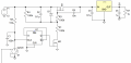
I found a circuit here (http://www.mosaic-industries.com/em...n-switch-turn-on/latching-toggle-power-switch) which looks like it was well-designed, however I can't make sense of it and was hoping someone could help me see the light.

The circuits's schematics are attached below (it's the last circuit in the above-mentioned webpage).

What I can't understand is how can this circuit ever work.

More specifically, I can't understand how does the N-channel mosfet ever turned on. As far as I can see, this mosfet requires 5V coming from the down-stream regulator; The regulator, in turn, can only supply 5V if if the P-channel mosfet is turned on; but the P-channel mosfet is dependent on the N-channel mosfet turning on, and we're back to square one... or am I missing something obvious here?

Many thanks,
SnowCrash
 

Attachments

LesJones

Joined Jan 8, 2017
4,190
When the circuit is first powered up The output will be in the "OFF" state. As both ends of the 1 uF capacitor are connected via resistors to the + input rail it will be in the discharged state. When the push button is pressed both ends of the capacitor will initialy go to zero volts. This will cause the P channel mosfet to turn on. This will cause the output to turn on which causes the n chnnel mosfet to turn on which holds the P channel mosfet in the on state.
When the circuit is in the "ON" state pressing the button pullsthe voltage on the gate of the N channel mosfet to ground via the diode. This causes the N channel mosfet to stop conducting so the P channel mosfet also stops conducting turning the output off. As the output is off there is noting to make the N channel mosfet conduct.

Les.
 

Thread Starter

SnowCrash

Joined Apr 6, 2016
31
Hi Les,

Apologies for my slightly delayed response & thank you very much for a very detailed and clear explanation! makes more sense now :)

However, I still need a bit more help. I've hooked-up the circuit on a breadboard, and it seems to be working fine, except... it only does so for about 4-5 seconds. Then the power output gets cut off. From what I can tell, the specific length of time the power output stays on from the moment I close the switch depends upon the size of the 10uF capacitor that's placed in parallel with the 100K & 300K resistors (I replaced it with a 47uF capacitor and the 'on' period was longer but the power output was still cut off eventually).

I used a 12V power supply (an old PC PSU) to power the circuit and got 12V on the power output whilst the circuit was on.

The only differences I can see between my hookup and the schematics are:
(1) I added a LED with a 1K series resistor from the power output to Ground as an indicator that the power output is on.
(2) I used a 9.1V zener diode instead of 15V as that's the closest value I had available.
(3) Instead of the 1uF ceramic capacitor, I used 2 x 2.2uF Wima capacitors hooked-up in parallel.
(4) I used a 10uF (/47uF) electrolytic capacitor instead of a ceramic one as I didn't have that capacitor value in the later form factor (is this crucial?)

For the unspecified part in the schematics, I used:
(1) 2 x 1N4148 diodes.
(2) Down-stream Voltage regulator: MIC5219 (5V output)


Consequently, I'm once again at a loss. Is the power cut-off after several seconds something that's supposed to happen even when the switch is closed? And if not, what could be causing it? and, finally, is there a way to ensure that the power output stays on until the switch is turned off?

(btw, I checked and re-checked the connections and they all seem fine. Plus, I assume the circuit wouldn't have worked at all had there been a bad connection).

Many thanks,
SnowCrash
 
Last edited:

Thread Starter

SnowCrash

Joined Apr 6, 2016
31
Tiny correction:

"(3) Instead of the 1uF ceramic capacitor, I used 2 x 2.2uF Wima capacitors hooked-up in parallel." - The capacitors are hooked-up in series (rather than parallel) to form an equivalent ~1uF capacitor value.
 

LesJones

Joined Jan 8, 2017
4,190
The switch should be a push button switch so that it only pulses the righthand side of the switch to ground. If it is held to ground it prevents the circuit from latching on.

Les.
 

Thread Starter

SnowCrash

Joined Apr 6, 2016
31
The switch should be a push button switch so that it only pulses the righthand side of the switch to ground. If it is held to ground it prevents the circuit from latching on.

Les.
Morning Les :)

I thought that might be the case and tried that but it didn't work as expected. I hooked-up a momentary switch as shown in the schematics and clicked it briefly. The power out (and the LED) turns on for as long as the button is clicked and then turns off when the button is released. I've done it several times with different durations (from a very short click to slightly longer ones) and there was no latching in any of the cases.

Any idea what am I doing wrong?
 

LesJones

Joined Jan 8, 2017
4,190
If You disconnect the diode from the junction of the 100K and 300K resistors does it latch on when the button is pressed ? With the diode disconnected the button will not switch it off but this test may give a clue to what is happening.

Les.
 

Thread Starter

SnowCrash

Joined Apr 6, 2016
31
Hi Les

I disconnected the diode as instructed. The circuit still does not latch, that is, the power output turns on for as long as the momentary switch is pressed down, but when it's released the power output turns off instantly (regardless if the press was very short or longer).

However, I did notice that without the said diode, the power output does not turn off after 4-5 seconds like it did before, but stays on for as long as the switch is pressed.

Does this tell you anything about what's going on?
 

LesJones

Joined Jan 8, 2017
4,190
I think the 1uF capacitor is short circuit. Without the diode the right hand side of the 1 uF capacitor should pulse down from your input voltage of 12 volts to zero volts for about 100 mS. If the rest of the latching circuit is working it should then be at about 8 volts. If the rest of the latching circuit is not working it should go up to 12 volts. If you have use an electrolytic capacitor for the 1 uF then that is probably the reason it does not work.

Les.
 

Veracohr

Joined Jan 3, 2011
772
I built the circuit and couldn't get it to work, and it didn't work for me in simulation either. I also tried simulating the simpler (lower voltage) version they have, and it didn't work either.

However, if you use a flip flop toggle instead of the arrangement they show with the resistors, capacitors, and diode, it works fine:


Screen Shot 2017-05-07 at 6.56.53 PM.png
 

Attachments

crutschow

Joined Mar 14, 2008
34,452
Below is a better way to debounce the input pushbutton.
The D input level change is delayed by R1C1 for about 80ms, thus preventing subsequent switch bounces from changing the FF state.
This design eliminates the possibility that the current surge from the debounce capacitor will weld the switch contacts.

upload_2017-5-8_20-16-20.png
 
Last edited:

Thread Starter

SnowCrash

Joined Apr 6, 2016
31
Hi Everyone,

First, my sincere apologies for the delay in reporting back & many thanks to all who contributed and offered insights and solutions!

I was greatly relieved to learn that the original circuit I posted was actually defective in some way and that it wasn't my incompetence that caused it not to work as intended (thanks Veracohr!)

I've built the alternative circuit posted by Veracohr, with the suggested modifications (thatnks dodgydave & crutschow!) and got much happier results :)

That said, as I was working on this, I came across a different solution in the form a single tiny IC that does all the work, i.e. transforms a momentary switch into a latching signal, and requires no extra components (apart from a bypass capacitor). It's Maxim's MAX16054AZT+T which comes in a SOT-23-6 package. It not only incorporates full debouncing of the signal, but also provides both an OUT signal and an inverted-OUT signal which was useful for my needs. As my project is a one-off personal one, the minimal footprint, useful functionality and simplicity of this solution overcame the issue of cost in this case (it's certainly not a cheap IC!).

Thanks again for everyone who took part & hopefully this thread might prove useful to someone in the future.

SnowCrash
 
Top