 Facebook
 Google
 GitHub
 Linkedin
Hi,
I am trying to understand the circuit and operation of a warm mist humidifier, model 975CVS. Someone gave it to me to try and repair, but really more important than repair is trying to understand how it works.
As I understand it there is a heating element that boils the water creating steam/mist. There are 2 settings, high and low. Water sits in a cavity above the element. When switched on a green light should glow and the humidifier operates. Supposedly when the water is all gone the light changes to red to indicate that water needs to be refilled (“reset” the humidifier). However, I am not sure about this second part, whether there is a red light that indicates water out.
I cannot find any instructions online on using the humidifier. The closest I can find is here: https://www.cvs.com/shop/cvs-health-warm-mist-fill-humidifier-prodid-796588 -- this is not for the same model, but it does state in the Directions section:
“RESET PROCEDURE. NOTE: WHEN THE WATER TANK IS EMPTY AND THE WATER IN THE HEATING CHAMBER IS ALMOST USED UP, THE HUMIDIFIER WILL AUTOMATICALLY SHUT OFF. THE POWER LIGHT WILL CHANGE FROM GREEN TO RED INDICATING THAT THE HUMIDIFIER IS OUT OF WATER. THE HUMIDIFIER WILL NOT OPERATE UNTIL THE WATER TANK IS REFILLED AND THE HUMIDIFIER IS RESET. Turn power OFF. Refill and replace Water Tank. For best results, use distilled water. Wait 5 minutes and turn power ON. NOTE: If reset light is illuminated, the Humidifier Tank needs to be refilled.”
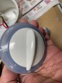
The rotary switch that selects off/low/high has a reset position, but the switch does not turn to that position, so not sure what that does. I don’t see a second red “reset” light bulb near the Reset switch position either.
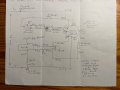
I have traced the circuit and attached is the circuit schematic/wiring diagram. It is fairly straightforward so hopefully it has been traced correctly, but maybe someone can validate based on knowledge of this type of circuit or from the attached photos.
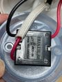
The heating element is within a sealed metallic heater element body, this is a bit of a black box, no way to know what else is in it without cutting it open. In addition to the 2 heater wires (labelled H1 & H2) there are 4 other wires connecting to it, labelled A, B, C, & D in the diagram. The connections of the wires to the terminals on/in the body are not visible, covered in insulation.
I found no continuity between terminals A and B on the heater, presumably there is some kind of temperature sensor inside the body of the heating element that switches off when the water is all gone, and perhaps is stuck open. I jumpered between A and B and the humidifier does work (green light comes on, heater gets hot), but I assume it won’t turn off when the water is gone.
However, I am confused on several other aspects:
Clearly there are aspects of this circuit and or the internal make up of the heating element and the bulb that I don’t understand, so I would really appreciate it if someone can shed some light.
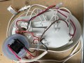
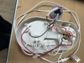
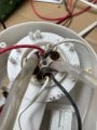
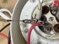
Note: Some of the pictures are taken after playing around with the device – so the red and white wires going to A & B have some insulation stripped to allow jumper to be connected, and the bulb wires are all broken off while checking how they connect. In some of the pictures there are pins piercing the insulation on wires A & B to enable checking continuity.
Thanks in advance.
I am trying to understand the circuit and operation of a warm mist humidifier, model 975CVS. Someone gave it to me to try and repair, but really more important than repair is trying to understand how it works.
As I understand it there is a heating element that boils the water creating steam/mist. There are 2 settings, high and low. Water sits in a cavity above the element. When switched on a green light should glow and the humidifier operates. Supposedly when the water is all gone the light changes to red to indicate that water needs to be refilled (“reset” the humidifier). However, I am not sure about this second part, whether there is a red light that indicates water out.
I cannot find any instructions online on using the humidifier. The closest I can find is here: https://www.cvs.com/shop/cvs-health-warm-mist-fill-humidifier-prodid-796588 -- this is not for the same model, but it does state in the Directions section:
“RESET PROCEDURE. NOTE: WHEN THE WATER TANK IS EMPTY AND THE WATER IN THE HEATING CHAMBER IS ALMOST USED UP, THE HUMIDIFIER WILL AUTOMATICALLY SHUT OFF. THE POWER LIGHT WILL CHANGE FROM GREEN TO RED INDICATING THAT THE HUMIDIFIER IS OUT OF WATER. THE HUMIDIFIER WILL NOT OPERATE UNTIL THE WATER TANK IS REFILLED AND THE HUMIDIFIER IS RESET. Turn power OFF. Refill and replace Water Tank. For best results, use distilled water. Wait 5 minutes and turn power ON. NOTE: If reset light is illuminated, the Humidifier Tank needs to be refilled.”
The rotary switch that selects off/low/high has a reset position, but the switch does not turn to that position, so not sure what that does. I don’t see a second red “reset” light bulb near the Reset switch position either.
I have traced the circuit and attached is the circuit schematic/wiring diagram. It is fairly straightforward so hopefully it has been traced correctly, but maybe someone can validate based on knowledge of this type of circuit or from the attached photos.
The heating element is within a sealed metallic heater element body, this is a bit of a black box, no way to know what else is in it without cutting it open. In addition to the 2 heater wires (labelled H1 & H2) there are 4 other wires connecting to it, labelled A, B, C, & D in the diagram. The connections of the wires to the terminals on/in the body are not visible, covered in insulation.
I found no continuity between terminals A and B on the heater, presumably there is some kind of temperature sensor inside the body of the heating element that switches off when the water is all gone, and perhaps is stuck open. I jumpered between A and B and the humidifier does work (green light comes on, heater gets hot), but I assume it won’t turn off when the water is gone.
However, I am confused on several other aspects:
- As far as I can tell there is/should be continuity between C and D. The wires to C & D both enter the element body in a common insulating sheath and are very close to each other as they enter, I cannot see where they actually terminate at the element body. The wire came off at D, so not sure if they are supposed to be connected, but I did have to jumper the C & D wires to make the heater work. If they are meant to be connected, what is the point of bringing the wires to C & D at the heater body, they (the neutrals) are already connected elsewhere. Maybe the temperature sensor also connects/disconnects C & D? Or maybe they are acting as a pseudo “ground” for the metal element body? There is no real ground, the device uses a cord with a 2-pin polarized plug.
- The light bulb has 4 wires going to it, so maybe it does have both green and red bulbs in it. What kind of bulb would this be – neon, LED? The bulb has a diode and a resistor in each set of wires, presumably to drop the voltage – similar to the diode in the low heat setting which I think is used to cut half the cycle and thus reduce power. The brown and white wires seem to be one set of wires, for the green light. But I am puzzled by the red wires, since they are both connected together at one end. How would this provide power to a second bulb, and what would switch it on? If when the water is gone and A & B are disconnected, then there should be no power anywhere in the rest of the circuit. One possibility: under normal operation (water present) A & B are closed, C & D are closed. When water runs out A to B opens, A to H2 closes, C & D remain closed – this could send power to the red bulb, EXCEPT – the 2 reds are joined.
Clearly there are aspects of this circuit and or the internal make up of the heating element and the bulb that I don’t understand, so I would really appreciate it if someone can shed some light.
Note: Some of the pictures are taken after playing around with the device – so the red and white wires going to A & B have some insulation stripped to allow jumper to be connected, and the bulb wires are all broken off while checking how they connect. In some of the pictures there are pins piercing the insulation on wires A & B to enable checking continuity.
Thanks in advance.
Attachments
-
 850.6 KB Views: 3
 -
 830.9 KB Views: 3
 -
 464.7 KB Views: 3
 -
 337 KB Views: 2
 -
 633.7 KB Views: 5
 -
 379.5 KB Views: 3
 -
 740.4 KB Views: 4
 -
 448.4 KB Views: 3
 -
 787.2 KB Views: 3


