Help with PWM Motor Control Board

MaxHeadRoom

Joined Jul 18, 2013
30,689
This motor control board, ME62T-2F, is more advanced than the more common boards, MC2100, MC60, etc. It is more advanced in that it controls motor speed not only using a PWM circuit, it also measures actual motor speed and adjusts for this.

RBarker2
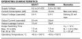
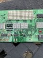
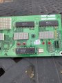
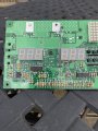
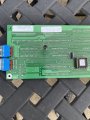
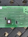
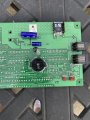
The MC2100 has a microprocessor control and measure belt speed and corrects accordingly. although the MC60 is mainly digital ic control it does have a fairly sophisticated method for this also. ;)
 

Ya’akov

Joined Jan 27, 2019
10,258
Guys,

Thank you once again for your help. I appreciate it very much.

This is what I’m thinking at this time:

This motor control board, ME62T-2F, is more advanced than the more common boards, MC2100, MC60, etc. It is more advanced in that it controls motor speed not only using a PWM circuit, it also measures actual motor speed and adjusts for this. Because of this, I plan to feed actual motor speed or some function of it back into the board. I am not concerned about how to do this at this point, but it will have to be addressed.

There are only 2 cables connecting this motor control board with the control panel board, the 6 conductor and the 8 conductor cables. The 6 conductor cable’s only function is to carry power, 11 VDC, from the motor control board to the control panel board. Five of the 8 conductors are for communications between the grade motor and the board, a sixth conductor is for the TACH signal to the control panel board for the display, a seventh conductor is a ground, and the only remaining conductor is SPEED CONTROL SIGNAL going from the control panel board to the motor control board. I’m thinking this is where the treadmill user selects the speed and it is communicated to the motor control board. The question is, what sort of signal is that? I need to generate that signal.

I have some familiarity with MC2100 and MC60 treadmill motor control boards. The MC2100 has three connector tabs on the board to input PWM control signals. The MC60 board has three connector tabs to input voltage via a potentiometer. Below I’ve attached 2 pictures of an MC60 board, one with connections in place and the other without. (There are actually 2 potentiometers wired in series in the picture to give me a coarse and fine adjustment for the speed.)

So, I’m hoping that from the pictures of the circuit boards and the circuit diagram you guys can tell me where to insert a potentiometer or PWM signal generator to control motor rpms.

If not, can you tell me what tests I should do to determine what needs to be done? I have at my disposal for this a couple of multimeters, some potentiometers, a bunch of different resistors, other electronic components salvaged from scrap, a DC power supply made from a computer power supply, and an inexpensive handheld oscilloscope. I also have the ME62T-2F board, of course, and an MC60 board. I have the input board for the treadmill but unfortunately, the flat ribbon type connectors to the flexible input sheet were cut during disassembly of the treadmill. (Big mistake!) So, what do you think? (I could just buy an SCR voltage controller and a bridge rectifier, but that would be a lot less interesting.)

Thank you again, big time, for your help!

RBarker2
Are you reading my posts at all?
 

Thread Starter

RBarker

Joined Aug 8, 2024
10
Ya’akov,
Yes, of course I'm reading your posts multiple times. All of the content may not sink in. I'm new to the vocabulary. You are recommending the use of a PWM signal generator rather than a potentiometer. I'm all on board with this if I know where to make the connection or even a best guess. In my ignorance of the subject I'm thinking there must be a PWM signal generator already a part of the system and I don't know where it is. Do you think the signal coming from the input board to the motor control board is a PWM signal? If so, how should I make the connection? Sorry for my ignorance.

RBarker2
 

Ya’akov

Joined Jan 27, 2019
10,258
Ya’akov,
Yes, of course I'm reading your posts multiple times. All of the content may not sink in. I'm new to the vocabulary. You are recommending the use of a PWM signal generator rather than a potentiometer. I'm all on board with this if I know where to make the connection or even a best guess. In my ignorance of the subject I'm thinking there must be a PWM signal generator already a part of the system and I don't know where it is. Do you think the signal coming from the input board to the motor control board is a PWM signal? If so, how should I make the connection? Sorry for my ignorance.

RBarker2
The information you need is in my post(s) and your posted images.

1723744498260.png
PWM: the PWM generator I mention was for testing. Pin 1 (SPEED CONTROL SIGNAL) is the PWM from the main board you would connect to where that line goes.

Rotational Speed Sensor: As my post said, you already have this and it is shown in your photos. It is on pin 2 (TACH FEEDBACK SIGNAL) and since it is a typical hall sensor you can just use it as is. I mentioned this as well.

I also pointed out that you could use the main board’s facility for adjusting the incline, which uses pins 3-7, to repurpose the linear actuator from the treadmill for some purpose on the tool.

I realize it might be a little difficult to decipher some of what I said, the information is all there if you take some time with it. You can ask questions about things you don’t understand, there’s not shame in being a beginner at things—everyone starts out that way.
 

Thread Starter

RBarker

Joined Aug 8, 2024
10
Ya’akov,

Ok, thanks for not giving up on me. So, my understanding is that the IN and OUT reference on the diagram for 1-8 is for the main board. The SPEED CONTROL SIGNAL (OUT) goes OUT from the main board to the motor speed control board as a result of the TM user selecting a speed on the membrane board. The TACH FEEDBACK SIGNAL (IN) is for a signal coming IN to the main board from the hall sensor. The SPEED CONTROL SIGNAL (OUT) may be modified based on the TACH FEEDBACK SIGNAL (IN) received from the hall sensor. So, is this correct?

I have a problem with the hall sensor. It is showing normally open and closes a little when I position the magnet in front of it, 5.03 VDC and 4.73 VDC respectively. I'm thinking I could solder wires from a new sensor in place there. What do you think?

I do not intend to use the main board in this project. If the SPEED CONTROL SIGNAL (OUT) is modified on the main board based on the TACH FEEDBACK SIGNAL (IN) that really changes the project.

Thanks,

RBarker2
 

Thread Starter

RBarker

Joined Aug 8, 2024
10
Ya’akov,

Please disregard my comment about a big change in the project. If no correction gets done because of TACH FEEDBACK SIGNAL (IN) that is OK with me.

RBarker2
 

Thread Starter

RBarker

Joined Aug 8, 2024
10
Thanks. I'm thinking not optical. There are eight magnets equally spaced, imbedded in the flange of the drive belt pully. Test procedure says there should be 0 VDC when magnet is not there and 5 VDC when the magnet is in position. My test showed 5.03 VDC when magnet was not present, 4.73 VDC when the magnet was at (very close) to the sensor. I have ordered a PWM signal generator, and it will be here Sunday. I plan to order a Speed Sensor Adapter for SAMDO Universal Motorcycle Speedometer, Tachometer from Amazon. Click Here.

Description says Work voltage 5v-12v.

Do you guys agree?

Thanks, RBarker2
 

Ya’akov

Joined Jan 27, 2019
10,258
View attachment 329337

Does it resemble this one?
If you have a sensor on the motor one one on the belt one could be optical.
View attachment 329351
@MaxHeadRoom this is the photo provided by the TS (and cleaned up by me):

1723796120303.jpeg
Honeywell S541A Hall Sensor [datasheet]
The TS also said:

I have a problem with the hall sensor. It is showing normally open and closes a little when I position the magnet in front of it, 5.03 VDC and 4.73 VDC respectively. I'm thinking I could solder wires from a new sensor in place there. What do you think?
But if you look at this table from the datasheet the operated output voltage is rated at 0.4V so the 0.3V measured looks right.

1723796684957.pngfrom the datasheet

@RBarker
So, my understanding is that the IN and OUT reference on the diagram for 1-8 is for the main board.
Yes, this is correct.

The SPEED CONTROL SIGNAL (OUT) goes OUT from the main board to the motor speed control board as a result of the TM user selecting a speed on the membrane board.
Yes, this is correct.

The TACH FEEDBACK SIGNAL (IN) is for a signal coming IN to the main board from the hall sensor. The SPEED CONTROL SIGNAL (OUT) may be modified based on the TACH FEEDBACK SIGNAL (IN) received from the hall sensor.
Yes, this is correct.

I have a problem with the hall sensor. It is showing normally open and closes a little when I position the magnet in front of it, 5.03 VDC and 4.73 VDC respectively.
No, according to your measurement the hall sensor is operating properly—refer to my comment to @MaxHeadRoom and the table from the datasheet, above.

I do not intend to use the main board in this project. If the SPEED CONTROL SIGNAL (OUT) is modified on the main board based on the TACH FEEDBACK SIGNAL (IN) that really changes the project.
Two things:

Using the main board for some of its functions may provide some great benefits, so don’t write. it off immediately.

”Closing the loop“ with feedback reduces the capability to the system dramatically.

An open loop system—that is, one that makes adjustments and hopes they result in expected outcomes—will mean that your ”feeds and speeds” become hopes and dreams. Under load the motor will reduce in speed which means everything that loads the motor: workpiece mass, cut depth, &c. will change what the setting means. In the end, your numbers for motor speed will be cut and try every time.

A closed loop system, where the information about actual rotation speed is used to adjust the PWM signal to result in a particular RPM not a notional “how hard to spin”, will allow for certainty. It is orders of magnitude superior to the open loop and more than worth the effort to achieve. It will actually improve the tool it is driving and in turn improve the work you do on it.


Attachments

Thread Starter

RBarker

Joined Aug 8, 2024
10
Guys,

OK. Open to keeping the main board. Pictures are below. Flipped board left to right for pictures. Thinking cables connecting the boards are RJ45 and RJ11. Did not order the hall sensor unit. Will retest mine again. PWM signal generator to arrive here tomorrow.

Roger
 

Attachments

Thread Starter

RBarker

Joined Aug 8, 2024
10
Guys,

OK, I got the PWM signal generator. I plan to set it to 20 hz as a place to start. Where do you suggest I connect it on the boards?

Thanks for any help, RBarker
 
Top