Help with PWM Motor Control Board

Thread Starter

RBarker

Joined Aug 8, 2024
10
All,

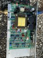
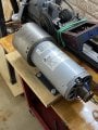
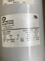
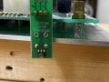
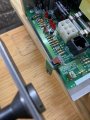
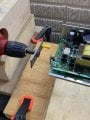
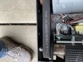
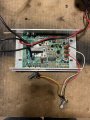
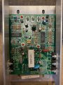
I’m a noob and sure could use some help making use of a motor control board from a treadmill. I salvaged the DC motor and motor control board from a True treadmill. I connected a Variac to a rectifier bridge, then to a motor choke from another treadmill, and finally to the motor. The motor worked great like that, but I want to make use of the motor control board.

There were two cables going from the control board to the PWM motor control board, one with 6 conductors, the other with 8. The wiring diagram says the 6 conductor cable is:

1,2 &3, +11 VDC Output (the three are interconnected),

4,5 &6, ground (the three are interconnected)


The wiring diagram says the 8 conductor cable is:

  • Speed Control Signal (out)
  • Tach Feedback Signal (in)
  • Grade Down Control Signal (out)
  • Grade Up Control Signal (out)
  • Grade POT. +5VDC (out)
  • Grade POT. GND (out)
  • Grade POT. Position Signal (in)
  • Ground


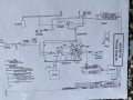
Attached is a copy of the wiring diagram from the service manual. So, what are your recommendations for what I should do to use this to control the motor speed? I plan to use the motor to drive a small metal lathe.

Thanks for any recommendations and/or comments.

RBarker2
 

Attachments

Ya’akov

Joined Jan 27, 2019
10,226
Welcome to AAC.

The key here is the PWM signal, and if you want to maintain speed under load, the tachometer signal.

You’ll need to generate a PWM signal that achieves the speed you want. You can buy PWM generator modules of various kinds pretty cheaply on Amazon or AliExpress—but if you want constant speed it’s more complicated.

In any case you will have to characterize the signals. The PWM signal’s frequency is important. You can use a cheap PWM generator to find it if there is no data in the manual. Calibrating duty cycle to speed can be done with the generator and a tachometer.

If you want to use the motor’s tachometer you will need to measure its output vs. rotational speed as well. If it’s linear you can extrapolate from a couple of data points. If not, you will need to characterize the curve in sufficient detail to understand how to get the speed you want. I expect it will be a simple linear output of once or twice a revolution, though.

The best way to do this (with the feedback) is with an MCU development board (Arduino, ESP32, or something like that), or an SBC (Single Board Computer) like a Raspberry Pi. It’s not a particularly difficult project for someone with experience but will be a bit challenging for a neophyte.

Still, I don’t think it is unreasonable to expect that a beginner could do this—it really depends on the person.
 

MaxHeadRoom

Joined Jul 18, 2013
30,594
Too bad it is not the MC2100's version, there is all the info you would need out there for a second purpose use. :(
That 8 pin diagram looks like it is just for the belt angle/control etc. ?
Anyway, if it is like the MC2100, the PWM signal frequency is very important. I presume this one is not known?
Also on the MC2100, the belt speed sensor is not required for operating the motor.
 

MaxHeadRoom

Joined Jul 18, 2013
30,594
All recent TM's pretty much use the same Type of DC brushed motor with rare earth magnetic field, And in this case it is the motor that was used with the board, evidentally.
The semi's on the board point to it being single PWM Mosfet driver.
The main issue is the PWM signal that drives it. Frequency etc??
 

MisterBill2

Joined Jan 23, 2018
27,315
Looking at the PCB photo I do see motor + and Motor - blade connectors. Whythey do not show on the wiring diagram is a puzzle. If the control system is closed loop, there will need to be some sort of motor speed feedback, if there is to be actual speed control.
 

MaxHeadRoom

Joined Jul 18, 2013
30,594
The typical way most often feed-back is done is to use a two wire magnetic reed SW & button magnet.
1723302019571.png

Just speed monitor and correction.
The motor connection is as common, two spade terminals, they are marked MTR - red MTR - blk.
Every one I have come across operates with just motor out and speed input signal, the most common now is via a PWM input signal.
e.g. The MC2100 uses a 20Hz PWM control input freq.
 

MisterBill2

Joined Jan 23, 2018
27,315
A reed switch for SPEED sensing?? That sounds a lot like deliberate planning to fail. I am aware of deliberately planned becoming obsolete, but deliberate sabotage???
 

Ya’akov

Joined Jan 27, 2019
10,226
That wiring diagram did not show the motor, nor the motor driver connections, nor any of that part. So it will not help you either,.
Bill—what are you talking about? The motor, the connections, and the driver board are all central and in your face in that image.
 

Ya’akov

Joined Jan 27, 2019
10,226
It is extremely low RPM to register, once/rev of the belt drive wheel. IOW operators perambulation.
NOT on the motor!
According to the wiring diagram it is a powered, three lead sensor. It is also called a “tach” implying it is probably part of the motor not the belt.
 

MaxHeadRoom

Joined Jul 18, 2013
30,594
According to the wiring diagram it is a powered, three lead sensor. It is also called a “tach” implying it is probably part of the motor not the belt.
The TM site manuals all show a two wire sensor, except the larger TM's have 3 wire and indicate one is (GRN) GND.
And they refer to 'Moving the belt' to check if the voltage on the sensor changes ??
 

Thread Starter

RBarker

Joined Aug 8, 2024
10
Guys,
Thank you all for the input. Sorry I'm so long getting back here. I had a computer glitch. Based on what you have said, I'm thinking I need to mount the board such that I can measure the rotational speed of the motor or some part of the drive system. I put power to the board with a multimeter measuring DC volts to the motor connection. The reading was high and changing some but went up to about 130 to 160 volts DC. When I cut the power it took maybe 15 minutes or so for the voltage to drop to below 10 volt. I'm thinking the capacitor or capacitors were holding the charge. I measured the voltage at 11.6 volts DC at the 6 pin plug. The wiring diagram show 11 volts DC. I connected a 550K ohm potentiometer at this connection with the wiper connected to the SPEED CONTROL SIGNAL (OUT) found on the 8 pin plug. Moving the potentiometer seemed to have no effect on the voltage to the motor terminals. I'm thinking this may have been because the board was sensing no motor speed? I have attached here pictures of the motor, the motor tag, the speed sensor front and top, a setup to run the magnet past the speed sensor, and a picture of the speed sensor in the treadmill before removal. Thanks again for your help!

RBarker2
 

Attachments

Ya’akov

Joined Jan 27, 2019
10,226
I connected a 550K ohm potentiometer at this connection with the wiper connected to the SPEED CONTROL SIGNAL (OUT) found on the 8 pin plug. Moving the potentiometer seemed to have no effect on the voltage to the motor terminals. I'm thinking this may have been because the board was sensing no motor speed?

PLEASE DON’T APPLY RANDOM SIGNALS TO THE CONTROLLER YOU COULD EASILY MAKE IT USELESS

Please see my post above. The SPEED CONTROL SIGNAL is PWM. The main board is producing a PWM signal which is signaling the controller what speed it expects the motor to go.

In PWM control, the output is proportional to the duty cycle* of the signal, not its voltage. A DC signal would be expected to have no effect, or to cause the motor to run at full speed if its voltage was appropriate. As I said above you can get a PWM generator for testing quite cheaply—for example, this one.
*there is a short explanation of PWM and duty cycle at the end of this post
1723450572714.jpeg
~$13.00USD from Amazon at the link in the text

This generator allows you to set the duty cycle as well as frequency. The motor controller will have some range of frequencies at which it will operate properly and where adjusting the duty cycle will change the motor speed.

The speed sensor is clearly a hall effect magnetic sensor. Hall effect devices change conduct in the presence of a magnetic field. They have three terminals: \(\mathsf{V_{ cc }}\), OUT, and GND. The \(\mathsf{V_{ cc }}\) is the power input (marked + on your PCB). Measure the voltage to the GND terminal (marked -) to work out what voltage the signal needs to be if you are going to remove the main board since you will have to power this sensor.

The OUT terminal (marked O) will have the ouput from the sensor and this provides the feedback to the main board generating the PWM so it can work out what effect applying a voltage to the motor actually has. Free-running when this input is staying quiescent makes sense. The controller thinks the motor isn‘t spinning and it is trying to make it spin.

Wherever the was mounted in the treadmill will be where the magnet is. Plan on duplicating this geometry.

You will have to work out the proper frequency and duty cycle range for the PWM signal, as well as its voltage. I suspect it will be 5V but you should measure it. With the treadmill set to run at full speed measure the SPEED CONTROL SIGNAL relative to GROUND (pin 0). WIth PWM voltage is proportional to duty cycle so this should read 5V or near it if I am correct.

But, if the maximum duty cycle used is much less than 100%, the voltage might appear low. This is OK, whatever you read should be enough of a clue to work that out. For example, if it is 2V then the output is probably 3.3V, if it is 4V it is probably 5V—given the age and technology visible on the board, I am betting on 5V.

NOTE: It is possible the controller board itself does not interpret the PWM signal as PWM but instead is controlled by the varying voltage in which case providing it with a voltage in the range created by the PWM signal would be the equivalent. PWM is still a better way to do it, but just in case that wold be useful down the road.

One thing to keep in mind is that the linear actuator that was used to adjust incline might be useful for some (probably not very high precision, but maybe better than I expect) adjustment of something about your tool. Since there is feedback using a potentiometer (save that!) you could use the main board’s ability to control for, I don’t know, operate the lathe’s carriage or maybe use a motor to operate the cross slide (the controller doesn’t need to know it’s not running a linear actuator, it just has to be able to get the feedback).

PWM: Pulse Width Modulation
PWM is a method for controlling the power of an output signal by turning on the output at its full voltage for a percentage of the interval of a square wave. The output is proportional to this percentage which is called the duty cycle.
1723453830632.png
waveforms for various duty cycles, each example is 2 cycles long for clarity
The figure above shows the effect of 0% to 100% duty cycle on the waveform at 25% intervals. the fine dotted line box is two cycles long, and you can see the waveform starts from 5V and ends at 0V—it could be shown the over way around, 0-5V, they are equivalent for this discussion.

The area from the left edge to where the line drops to 0V will be n% of the total cycle. You should be able to see that. The power output by these waveforms is n% of whatever the total power is at the peak. This is a very efficient way of varying power since it doesn’t need to dissipate the power not desired as heat.
 

MaxHeadRoom

Joined Jul 18, 2013
30,594
Many of the TM boards now use PWM for control, in the case of the MC2100 it is 20Hz and very critical as to freq.
The DC is going to be high as it is rectified mains power.
The Motors used in N.A. are commonly 90v to 120vdc, the actual mean level is limited by the PWM signal for the motor power itself.
 

Thread Starter

RBarker

Joined Aug 8, 2024
10
Guys,

Thank you once again for your help. I appreciate it very much.

This is what I’m thinking at this time:

This motor control board, ME62T-2F, is more advanced than the more common boards, MC2100, MC60, etc. It is more advanced in that it controls motor speed not only using a PWM circuit, it also measures actual motor speed and adjusts for this. Because of this, I plan to feed actual motor speed or some function of it back into the board. I am not concerned about how to do this at this point, but it will have to be addressed.

There are only 2 cables connecting this motor control board with the control panel board, the 6 conductor and the 8 conductor cables. The 6 conductor cable’s only function is to carry power, 11 VDC, from the motor control board to the control panel board. Five of the 8 conductors are for communications between the grade motor and the board, a sixth conductor is for the TACH signal to the control panel board for the display, a seventh conductor is a ground, and the only remaining conductor is SPEED CONTROL SIGNAL going from the control panel board to the motor control board. I’m thinking this is where the treadmill user selects the speed and it is communicated to the motor control board. The question is, what sort of signal is that? I need to generate that signal.

I have some familiarity with MC2100 and MC60 treadmill motor control boards. The MC2100 has three connector tabs on the board to input PWM control signals. The MC60 board has three connector tabs to input voltage via a potentiometer. Below I’ve attached 2 pictures of an MC60 board, one with connections in place and the other without. (There are actually 2 potentiometers wired in series in the picture to give me a coarse and fine adjustment for the speed.)

So, I’m hoping that from the pictures of the circuit boards and the circuit diagram you guys can tell me where to insert a potentiometer or PWM signal generator to control motor rpms.

If not, can you tell me what tests I should do to determine what needs to be done? I have at my disposal for this a couple of multimeters, some potentiometers, a bunch of different resistors, other electronic components salvaged from scrap, a DC power supply made from a computer power supply, and an inexpensive handheld oscilloscope. I also have the ME62T-2F board, of course, and an MC60 board. I have the input board for the treadmill but unfortunately, the flat ribbon type connectors to the flexible input sheet were cut during disassembly of the treadmill. (Big mistake!) So, what do you think? (I could just buy an SCR voltage controller and a bridge rectifier, but that would be a lot less interesting.)

Thank you again, big time, for your help!

RBarker2
 

Attachments

Top