Help with oscilloscope and multimeter readings for guitar signal

Ian0

Joined Aug 7, 2020
13,306
R6/R7 won't work. because you might need 1mA for the IC. 1mA would require a voltage drop of 100V across R6!
The IC supply must be connected to a stable low-impedance source.
If you need to offset the output, put a resistors across C3.
If you need to produce a lower supply voltage, use an LP2951.
 

Thread Starter

rpschultz

Joined Nov 23, 2022
851
R6/R7 won't work. because you might need 1mA for the IC. 1mA would require a voltage drop of 100V across R6!
The IC supply must be connected to a stable low-impedance source.
If you need to offset the output, put a resistors across C3.
Yeah a lower voltage regulator would be nice. I'll have to study it more, but at first read the max current of the LP2951 is 100 mA... not enough for the ESP32 I don't think. Not sure.

Could you explain a bit more detail of the math you did in the first line? I'm a mechanical engineer who loves circuits... but doesn't necessarily have all the education that many on this forum have. I understand a LOT more than I did a couple years ago, thanks to this forum... but I'm not getting this one. Thanks.
 

Ian0

Joined Aug 7, 2020
13,306
1mAΩ x 100k = 100V. Simple Ohm's law.
Other precision regulators are available. LP2951 is the one I use. The output voltage is very accurate and it is very low noise (<150uV). I don't know how much current an ESP32 uses. I'm used to microcontrollers that use about 20mA, but I don't use microcontrollers that incorporate radio transmitters.
 

Thread Starter

rpschultz

Joined Nov 23, 2022
851
Ok. I think I get it. The circuit in post #4 this problem doesn’t exist. 15uA of current can flow through the voltage divider. The op amp can take as much as it wants because it’s coming straight off the voltage regulator. But in post 40 the IC is powered through the voltage divider. Thanks for the help.
 

Thread Starter

rpschultz

Joined Nov 23, 2022
851
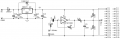
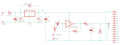
Would this work? Still 5v regulator powering the 74HCU04 and the MCU. But the output of the 74HCU04 is scaled down to 3v. Schematic3.png
 

Ian0

Joined Aug 7, 2020
13,306
So like:
1: a 1u?
2: 10k, 15k?
It's a high pass filter, with a resistor of 100k in parallel with 150k, so f=1/(2πRC) = 2.6Hz for 1uF, and you probably only need to pass 80Hz.

for 2) it gets more complicated, as you need to attenuate the average DC voltage from 2.5V to about 1.55V.
so you need to reduce the signal to 62%. That means 38% across R4 and 62% across R6||R7. so the parallel combination of R6||R7 is 62/38*R4.
and the ratio of R6 to R7 is 3.45/1.55.
Simultaneous equations! Lovely!
 

Thread Starter

rpschultz

Joined Nov 23, 2022
851
As I understand it, R5 and C3 form a LPF at 677 Hz. And R5 and R7 are a voltage divider stepping the output down from a center of 2.5v to 1.676v. Yes?
For reference, R4 and C2 form a LPF at 34 Hz. A band pass of 34-677 Hz works for bass up to an octave harmonic on the high e of a guitar.
1724697642937.png
Could also use:
R5: 10k
R7: 15k
C3: 22n (gives 723 Hz)
 

Ian0

Joined Aug 7, 2020
13,306
As I understand it, R5 and C3 form a LPF at 677 Hz.
R7 is involved as well. For AC signals it appears to be in parallel with R5, so the filter cutoff will be higher than you think, or you will need a larger capacitor.
The rest is OK. Give it a go and see how well it works.
 

Thread Starter

rpschultz

Joined Nov 23, 2022
851
R7 is involved as well. For AC signals it appears to be in parallel with R5, so the filter cutoff will be higher than you think, or you will need a larger capacitor.
The rest is OK. Give it a go and see how well it works.
Ah. OK. So R5||R7 is 3k. Spice say cutoff of ~1200 Hz. I see how it works. I'll fiddle with some numbers. thanks.
 

Thread Starter

rpschultz

Joined Nov 23, 2022
851
I've been reading up on Schmitt Triggers and comparators. What's the difference between them and the 74HCU04? They seem similar to me as a novice. Which one would be best for this application?
 

Ian0

Joined Aug 7, 2020
13,306
I've been reading up on Schmitt Triggers and comparators. What's the difference between them and the 74HCU04? They seem similar to me as a novice. Which one would be best for this application?
Both?
The 74HC14 will turn your signal into a nice squarewave, provided that it goes higher than the positive switching threshold and lower than the negative switching threshold. When you have a nice squarewave,you can more easily find its frequency.
But first, you need to amplify the signal to make it large enough to trigger the Schmitt trigger.
However, if you have lots of harmonics that makes the signal exceed the thresholds more than once per cycle, then it might really mess it up.
 

Thread Starter

rpschultz

Joined Nov 23, 2022
851
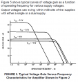
I thought the 74HCU14 did amplify it, with a gain of around 40 dB for a 5v VCC. I'm expecting signals in the 100-300mv p-p range.
1724766212986.png
 

Thread Starter

rpschultz

Joined Nov 23, 2022
851
I've got a couple 74HCU04's on order, will be interesting to see how it looks on the scope. But I wondered about using cascading stages, one into the other. I would think each successive stage would make it more square than the one before it.
 
Top