Facebook
 Google
 GitHub
 Linkedin
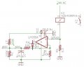
I am trying to find an error in a circuit I was given. I have been told that his is the schematic for a working piece of hardware that I need to replicate. I have breadboarded the given schematic but the ADC it is feeding is giving different/invalid results using the same software as the working unit. I am wondering if I was given a schematic with an error in it. Can anyone help me analyze this design for function/errors? I am having difficulty getting through it. The goal is to measure current to the 24vac solenoid.
Attachments
-
 23.7 KB Views: 26