Facebook
 Google
 GitHub
 Linkedin
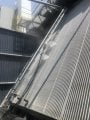
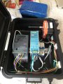
Looking to add an upper and lower limit switch to this control box.
System runs a cogged belt up and down a track.
I have a 3p motor control by a vfd
Wireless controls(momentary) into the x terminals on the vfd(3wire control)
I need to add two limit switches but they need to sequence. After tripping the limit, it decelerates and then passes back past the switch.
I’m thinking of using latching relays in between the wireless and the vfd
Attachments
-
 213.5 KB Views: 38