Help with EASYEDA amp/charge/boost design

Thread Starter

stormrazer121

Joined May 20, 2023
8
I am in the process of making my own Amplifier! it will be a first time for me with designing it all in EASYEDA.

There is a few things i want to try and clear up before going forward though and hoping you guys might be able to help me with that!

There is 3 main components in the design, they are...

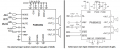
The Amp itself which will be designed around a PAM8403/Pam8406

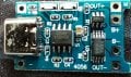
A charging module which has protection.

A Boost convertor/step-up module to boost the 18650 to 5.1volts

So far i have designed and got a working amp but i am wanting to put this all onto one board, is there anything i should be aware of when doing so?

I have seen what some others have done on YouTube and although i like the designs I'm unsure how to implement them into my own design without creating a ground loop or any other issues i may not be aware of! So with that i am looking for advice, any and all is welcome!
 

Audioguru again

Joined Oct 21, 2019
6,674
The PAM8403 and PAM8406 amplifiers produce low power at fairly low distortion into common speakers but are advertised driving 2 ohm speakers with extremely distorted higher power.
1) 8 ohms, fairly low distortion, 5V supply= 1.5W per channel, maybe 1.6W when powered from 5.1V.
2) 4 ohms, fairly low distortion, 5V supply= 2.5W per channel, maybe 2.7W when powered from 5.1V.

Many You Tube electronics videos are produced by kids who have not learned much electronics details yet.
The amplifier will be small and have fairly low current so a ground loop will probably not happen.
 

BobTPH

Joined Jun 5, 2013
8,813
The only way you get a ground loop is by having two paths to ground at some point. Why would you do that?

I don’t think ground loops is what you are worried about, I think you are talking about ground lift, which can occur if a grounding point shares a trace with a component drawing high current. Don’t do that either, use star grounding, i.e. a different trace to each ground from a common point where the power comes in.
 

Thread Starter

stormrazer121

Joined May 20, 2023
8
The PA -snip- not happen.
Noted! already had that feeling, I did like Greatscotts idea on YouTube but again there was some issues which i cannot remember off the top of my head right now with the step up module he created but I digress,

I have a schematic, thought I would upload it, its rough I know but I'm basing it from a known working unit I do need to get values and add them all in as only a few are there at the moment! (its a salvaged pam8403 unit from a shop bought speaker dock)

I suspect there is more to it than what I can personally comprehend, I'm still learning and this was a good way to get to grips with it and worked well for me in learning how to use EASYEDA and how to build in it! plus i fixed it and got it working so that was a plus!

Hopefully I will use this schematic and transform it into a PAM8406, so far I have dropped that onto the board and all works apart from when it is switched off the amp itself lets out what I can only describe as it letting one go lol! and odd effect which I'm sure has something to do with the board being built for a 8403 and not a 8406! amptest1.png
 

Attachments

Audioguru again

Joined Oct 21, 2019
6,674
The PAM8406 has exactly the same specs as the PAM 8403 with 4 ohm or 8 ohm speakers but the PAM8406 can drive 2 ohm speakers slightly louder (almost double the power). The PAM 8406 can be switched between class-AB and class-D but you probably will not hear any difference. Class-AB wastes battery power making heat when playing. They cost the same.
 

Attachments

Thread Starter

stormrazer121

Joined May 20, 2023
8
The PAM8406 ha -snip- t the same.
Ahh i see, well i dug deeper into the specs of both, from what i can see the pam8406 states it can do 3.14w on a 4ohm speaker but the pam8403 can do 3.2w into a 4ohm speaker.

I am beyond confused! Partly because i transplanted the pam8406 onto my working pam8403 board (based on that schematic you see) and the sound is....better and handles higher volume better? so I'm unsure what exactly is happening here
 

Audioguru again

Joined Oct 21, 2019
6,674
The PAM8406 produces 3.14W into 4 ohms and the PAM8403 produces 3.2W onto 4 ohms of severely distorted squarewaves.
The spec says 10% distortion that sounds awful like acid rock turned up too high.

The PAM8403 needs R5 and R7 to set its gain but are not needed for the PAM8406 that already has them inside. Then your PAM8406 has less gain than the PAM8403.

Because the sensitivity of our hearing is logarithmic then double the power sounds only a little louder. 10 times the power sounds twice as loud.
 

Thread Starter

stormrazer121

Joined May 20, 2023
8
Got it that makes sense, i suppose sticking with the pam8403 is the logical thing to do then? i do digress again though!

I am currently working on the li-ion 18650 cell charging, the unit i have bought is just a cheap thing but i bought it so i could try to understand how it works abit better, for the charging it uses a 4056H, the protection is two small ICs a DW01-A AND A 8205A.

From what i understand the 4056H is what controls the charging and the DW01-A and the 8205A im unsure what does what??

Cheers :D
 

Audioguru again

Joined Oct 21, 2019
6,674
The Li-Ion battery is 4.2V when fully charged then the PAM8403 produces 1.8W per channel into 4 ohms with fairly low distortion. The output into 8 ohms is 1W per channel.

The battery is about 3.7V when half-discharged and the output power into 4 ohms is 1.4W per channel and is 0.8W per channel into 8 ohms.

The battery is about 3V when it is almost dead and the load must be disconnected. The power into 4 ohms and is 0.8W per channel into 4 ohms and is 0.45W per channel into 8 ohms.

The 8205A protection circuit is for many battery cells in series. the DW01-A protection circuit is for the single battery cell you are using. Look in Google for parts like that.
 

Thread Starter

stormrazer121

Joined May 20, 2023
8
The 8205A protection circuit is for many battery cells in series. the DW01-A protection circuit is for the single battery cell you are using. Look in Google for parts like that.
Thank you, i really appreciate all your help so far! so my intention i do not think i have made clear so,

I intend on using 2 18650 cells to act as a single 3.7 cell (common in the dual 18650 battery packs to recharge a device)

My idea is that i can boost the voltage to around 5.2v to allow for a higher amp draw and thus closer to 3w output on a 4 ohm speaker!

So this charger idea i had was based off of that but of course i intend on designing this all on a single PCB, the speaker dock itself is already built, i made it years ago and never finished it.

so what i am confused on of course is that this charging board is is already built and what you are saying is the 8205A shouldn't be a part of it? i have attached an image of the exact part i intend on tearing down to understand it better.
 

Attachments

Audioguru again

Joined Oct 21, 2019
6,674
You never posted the datasheet for the charger board you have. It will probably say the details for it.
I looked up 8205A and the first one is an S-8205A that is completely different to the 8205A that you have.

The board has a USB connector that might be for the charger input. Then the charger output has limited current that will take a long time to charge two paralleled 18650 battery cells. I do not know if you can find a voltage booster that provides regulated 5.5V with enough current when the input voltage from the battery is 2.5V to 4.2V.
 

Thread Starter

stormrazer121

Joined May 20, 2023
8
I would have to be honest in the fact that i do not have access to the correct data sheet, this was a cheap board i bought from amazon. Would there be somewhere you would suggest i go look to learn more? I have googled but it is hard to find reliable information and the majority of info I do find is for some reason in Hindu? I find that rather odd?

The USB connecter is indeed for the charger input, I'm not really intent on using the speak while it is charging! so I don't think that will be a major factor, its more about building the amp, charger and boost function making sure it is protected and no ground loops or other issues are there. speed of charge wouldn't be a major factor but if there is indeed a better IC or circuit you would suggest for this application I am all ears :D
 

Audioguru again

Joined Oct 21, 2019
6,674
Amazon and its sellers know nothing about the cheap electronic circuits they sell. Many kids in India post electronics videos on You Tube and get paid. Some videos are faked and do not work.

If the amplifier or any other load is turned on while the battery is charging then the charger circuit will not detect a full charge.
 
Top