 Facebook
 Google
 GitHub
 Linkedin
Hi all,
First excuse me for my english, i´m speak english a little bit or use a translator on don´t understand.
Thanks everyone for response.
I´m trying to decrypt the connector of an electronic board to know what each pin of said socket belongs to, it is a contact liquid pump (it has 2 metal tabs that when in contact with the liquid DOES NOT pump and when they are no longer submerged the pump is activated where it sucks the liquid from a bottle, which has the same system to detect liquid), the connector is 6 pin, I have already identified 4 of the 6 (in the absence of knowing the function of each one).
The pump has 2 indicator leds (red and green).
The "bottle" connector (2pin) is also by contact, because if the bottle is empty and the metals are not soaked, the pump will NOT start.
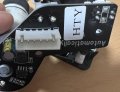
The pins (as in the photo):
1- It is connected to one of the condenser legs.
2- It goes to a resistance.
3 and 4- No continuity in any component on the board (maybe the bottle sensor pins?).
5-mosfet.
6-Integrated or mosfet (I have doubts).
The description of the device:
This pump is connected independently within a machine and due to length or optimization of the cable, they have it placed independently and must be connected internally to each other. so the bottle connector (2Pin) has its own connector and the pump another (6pin).
This pump (I deduce that it must run at 5V).
My intention is to find out which pin belongs to "positive" and which to "negative", to go doing tests, but at least not burn it.
My deduction is the following:
2 pins, positive and negative.
2 pin, bottle sensor
2 pin, data (Since it can be connected to the machine to indicate and activate this accessory from the machine itself).
Intention:
Use this system independently.

First excuse me for my english, i´m speak english a little bit or use a translator on don´t understand.
Thanks everyone for response.
I´m trying to decrypt the connector of an electronic board to know what each pin of said socket belongs to, it is a contact liquid pump (it has 2 metal tabs that when in contact with the liquid DOES NOT pump and when they are no longer submerged the pump is activated where it sucks the liquid from a bottle, which has the same system to detect liquid), the connector is 6 pin, I have already identified 4 of the 6 (in the absence of knowing the function of each one).
The pump has 2 indicator leds (red and green).
The "bottle" connector (2pin) is also by contact, because if the bottle is empty and the metals are not soaked, the pump will NOT start.
The pins (as in the photo):
1- It is connected to one of the condenser legs.
2- It goes to a resistance.
3 and 4- No continuity in any component on the board (maybe the bottle sensor pins?).
5-mosfet.
6-Integrated or mosfet (I have doubts).
The description of the device:
This pump is connected independently within a machine and due to length or optimization of the cable, they have it placed independently and must be connected internally to each other. so the bottle connector (2Pin) has its own connector and the pump another (6pin).
This pump (I deduce that it must run at 5V).
My intention is to find out which pin belongs to "positive" and which to "negative", to go doing tests, but at least not burn it.
My deduction is the following:
2 pins, positive and negative.
2 pin, bottle sensor
2 pin, data (Since it can be connected to the machine to indicate and activate this accessory from the machine itself).
Intention:
Use this system independently.
Attachments
-
 546 KB Views: 5


")


