Help with DAC using MAX5250

Thread Starter

DocQBN

Joined Jan 2, 2017
32
Hi, I'm currently working on a project that uses a MAX5250 DAC my issue is that the output voltage is very inaccurate and fluctuates terribly sometimes /- 0.4 volts to +/- 2 volts which for my project is very bad as I need a very accurate voltage. I've added a decoupling circuit near VCC which is just a 10uf and two 0.1uf capacitors in parallel. I tried adding smoothing caps (10V 100uf) at the outputs with no noticeable effect. I'm at a lost and considering switching over to PWM to analog conversion. If someone could help me figure out this fluctuation issues that would be great or if there is a new and better method for DAC that would make this simpler please let me know.
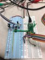
My Set-Up:
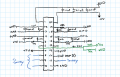
I have it wired like Figure 10 in the datasheet for a unipolar rail-to-rail circuit with the 10K resistors.
I'm using a voltage divider to get 2.5 volts for Vref.
My VCC is a constant 5V.
I'm using a teensy 2++.


My Code via Arduino interface:

C:
#include <SPI.h>// inslude the SPI library:
const int slaveSelectPin = 7;// set pin 7 as the slave select for the digital pot:
word val = 0;
word val2 = 0;
float voltage;


void setup() {
  Serial.begin(9600);
  pinMode (slaveSelectPin, OUTPUT);  // set the slaveSelectPin as an output:
  SPI.setClockDivider(SPI_CLOCK_DIV4);
  SPI.begin();   // initialize SPI:

   digitalPotWrite(0,900); // 0-1023 EDIT HERE
  }
/* Unipolar w/gain @Input 5.02V
* Trial|   1   |   2   |   3
* 1    = 0.15V  - 0.33 -
* 50   = 0.25V  - 0.55 - 0.28
* 100  = 0.45V  - 0.79 - 0.50
* 150  = 0.55V  - 0.99 - 0.71
* 300  = 1V     - 1.62 - 1.56
* 750  = 2V     - 3.69 - 3.30
* 900  = 3V     - 4.49 - 4.10
* 1023 = 5      - 4.96 - 4.86
*
* Uni-Polar w/o gain
* 400 = 1
* 800 = 2
* 1000 = 2.5
*
*/
void loop()
{
      //digitalPotWrite(5,5);    //need to send a 16 bit word
      delay(1000);
}

void digitalPotWrite(int address, int value) {
    Serial.print("  Address:  ");
    Serial.print(address);
    Serial.print("  Value:  ");
    Serial.print(value);
  

  //channel 0 = 00110000   = 48
  //Channel 1 = 01110000   = 112
  //Channel 2 = 10110000   = 176
  //channel 3 = 11110000   = 240 for 8


  val = highByte(value << 2);
  val2 = lowByte(value << 2);

  if (address == 0)
    {val = val+ 48;}
  if (address == 1)
    {val = val+ 112;}
  if (address == 2)
    {val = val+176;}
  if (address == 3)
    {val = val+240;}


  digitalWrite(slaveSelectPin,LOW);  // take the SS pin low to select the chip:
  //SPI.transfer(B00111111);  // works
  //SPI.transfer(B11111100);
  SPI.transfer(val);
  SPI.transfer(val2);
  //val = SPI.transfer(63);  //works too
  //val2 = SPI.transfer(B11111100);
  digitalWrite(slaveSelectPin,HIGH);   // take the SS pin high to de-select the chip:


  Serial.print("  First:  ");
  Serial.print(val);
  Serial.print("  Second:  ");
  Serial.println(val2);
  Serial.print(" Expected Voltage: ");
  voltage = 5.00 * (value / 1024.00);
  Serial.print(voltage);
}
Mod edit: code tags
 

Attachments

Last edited by a moderator:

Papabravo

Joined Feb 24, 2006
21,228
I need a schematic diagram to help you out. If properly wired and configured a 10-bit DAC should have a rock solid output. I'd start with the assumption that the DAC chip itself does not have a problem. If you hold the processor in RESET what does the output do?
 

Thread Starter

DocQBN

Joined Jan 2, 2017
32
I need a schematic diagram to help you out. If properly wired and configured a 10-bit DAC should have a rock solid output. I'd start with the assumption that the DAC chip itself does not have a problem. If you hold the processor in RESET what does the output do?
Attached is a schematic, I will try out your suggestion and let you know what happens this evening.
 

Attachments

Thread Starter

DocQBN

Joined Jan 2, 2017
32
@Papabravo Today I soldered the whole thing down to a perf board which seemed to fix most of the voltage fluctuation issues. I tried setting pin 7 low to reset it to see what it did but it seemed to be more problematic after that (wouldn't accept any inputs) so I changed the chip out. I also changed the 10K voltage divider to 8K resistors. My issue now is it's very finicky in the sense that sometimes it updates the voltage when I send it commands and sometimes it doesn't. I tried sending 1023 in the digitalpotwrite and got 4.9 volts then I tried sending 505 but got 3.6 volts; sometimes the chip will not refresh at all and stays at 5ish volts.
 

Papabravo

Joined Feb 24, 2006
21,228
@Papabravo Today I soldered the whole thing down to a perf board which seemed to fix most of the voltage fluctuation issues. I tried setting pin 7 low to reset it to see what it did but it seemed to be more problematic after that (wouldn't accept any inputs) so I changed the chip out. I also changed the 10K voltage divider to 8K resistors. My issue now is it's very finicky in the sense that sometimes it updates the voltage when I send it commands and sometimes it doesn't. I tried sending 1023 in the digitalpotwrite and got 4.9 volts then I tried sending 505 but got 3.6 volts; sometimes the chip will not refresh at all and stays at 5ish volts.
The scaffolding you have provided via the Serial Port is excellent. Congratulations on that.

You now need to question the reliability of the data transfer to the device. The datasheet will have timing requirements which need to be met in order to guarantee reliable operation. Those connections between the DAC and the microprocessor were not documented in your schematic.

Some things to check:
  1. CS* must remain LOW during the transfer of both bytes
  2. You must wait until both bytes have been shifted out before letting CS* return to the HIGH state.
  3. Do you understand the difference between a shift register and an output register?
  4. Can you verify these timings with an oscilloscope?
  5. Can you read back the data you just wrote to the device?
  6. Do you understand the difference between address bits and control bits for this device and why you need to explicitly specify both things?
I'm not assuming anything about what you know or don't know so don't draw any inferences from what you may think is the tone of the questions or comments. What I do know is the the problem description says that you have not read the datasheet carefully, and using decimal numbers in your program is a lousy way to double check that values are correct by inspection.
 
Last edited:

Thread Starter

DocQBN

Joined Jan 2, 2017
32
Thank you for your help. I'll admit the programming aspect is not my strongest area.

I'm currently trying to get ahold of an oscilloscope to see what the output is. I also updated the schematic to reflect the connections to the teensy 2++.

Could you explain what you mean with the decimal numbers? Did I miss something significant in the datasheet? Like I stated before my coding experience is not that great, but I'm willing to learn.
 

Attachments

Papabravo

Joined Feb 24, 2006
21,228
Thank you for your help. I'll admit the programming aspect is not my strongest area.

I'm currently trying to get ahold of an oscilloscope to see what the output is. I also updated the schematic to reflect the connections to the teensy 2++.

Could you explain what you mean with the decimal numbers? Did I miss something significant in the datasheet? Like I stated before my coding experience is not that great, but I'm willing to learn.
You are adding decimal constants to the DAC value in order to form the command/data word that you send to the device, and you are doing it WRONG. Convert each of those constants to hexidecimal notation and you will see by inspection that the correct values are going where they need to go. With decimal constants it is hard to tell by inspection. The address bits are the most significant bits and the CONTROL bits are the next most significant bits. In order for correct operation you need to set both the address and control bits correctly. You might try echoing the bytes you are sending to the SPI on the terminal in hexadecimal or binary notation.
 

Thread Starter

DocQBN

Joined Jan 2, 2017
32
This seemed to work. I realized that the registers were not being updated. My voltage is off by about 0.1V sometimes.

One concern I have is that the teensy may be disregarding the first two 0's in the first 8 bits thus the DAC may not be reading the first zeros and just reading the 1's.
A second concern is the voltage discrepancy.

I tried writing an analogRead to read the voltage back connecting PIN F0 to output A on the DAC but this seems to not be working either.

Code:
#include <SPI.h>// inslude the SPI library:
const int slaveSelectPin = 7;// set pin 7 as the slave select for the digital pot:
word val = 0;
word val2 = 0;
float Voltage;
float Aread;

void setup() {
  Serial.begin(9600);
  pinMode (slaveSelectPin, OUTPUT);  // set the slaveSelectPin as an output:
  SPI.setClockDivider(SPI_CLOCK_DIV4);
  SPI.begin();   // initialize SPI:
      }

void loop()
{
   
     for (int i=0; i <= 1023; i++){
      digitalPotWrite(0,i);    //need to send a 16 bit word
      delay(2000);}
      Aread = analogRead(A0);
      delay(2000);
      }

void digitalPotWrite(int address, int value) {
    Serial.println(" ");
    Serial.print("Address:  ");
    Serial.print(address);
    Serial.print("  Value:  ");
    Serial.print(value);
    Serial.print("  ");
    Serial.println(value, BIN);
  
  val  = highByte(value << 2);
  val2 = lowByte (value << 2);
    /*
    Serial.print("val  ");
    Serial.println(val, BIN);
    Serial.print("val2 ");
    Serial.println(val2, BIN);
    */


    // the third bit has been changed to 0 in order to lead to register
  if (address == 0)
    {val = val+ B00010000;}      //Value 48;  Hex = 0x30; Bin = 00110000
  if (address == 1)
    {val = val+ B01010000;}      //Value 112; Hex 0x70;   Bin = 01110000
  if (address == 2)
    {val = val+ B10010000;}      //Value 176; Hex = 0xB0; Bin = 10110000
  if (address == 3)
    {val = val+ B11010000;}      //Value 240; Hex = 0xF0; Bin = 11110000
/*
  digitalWrite(slaveSelectPin,LOW); // take the SS pin low to select the chip:
  delay (1);
  SPI.transfer(B01000000);
  SPI.transfer(B01000000);
  digitalWrite(slaveSelectPin,HIGH);
  delay (15);
   */
  //Loading Registers; DAC registers unchanged
  digitalWrite(slaveSelectPin,LOW); // take the SS pin low to select the chip:
  delay (1);
  SPI.transfer(val);
  SPI.transfer(val2);
  digitalWrite(slaveSelectPin,HIGH);   // take the SS pin high to de-select the chip:
  delay (15);

  //Updating DAC registers
  digitalWrite(slaveSelectPin,LOW);
  delay (1);
  SPI.transfer(B01000000);
  SPI.transfer(B01000000);
  digitalWrite(slaveSelectPin,HIGH);
  delay (15);

  Serial.print("First:  ");
  Serial.print(val, BIN);
  Serial.print("  Second:  ");
  Serial.println(val2, BIN);
  Serial.print("Expected Voltage: ");
  Voltage = (5.00 ) * (value / 1024.00);
  Voltage = Voltage + (Voltage * 0.45);
  Serial.println(Voltage);
  Serial.print("Voltage Read:     ");
  Serial.print(Aread);


//////////////////////////////////////////////////////////////////////////////////////////////////
//SPI.transfer(B00111111);  // works
//SPI.transfer(B11111100);
//val = SPI.transfer(63);  //works too
//val2 = SPI.transfer(B11111100);
}
 

Papabravo

Joined Feb 24, 2006
21,228
Would you be able to help me figure out the voltage constantly being off from what the datasheet calculates?

From what I understand Vout = Vref (x/1023) + 2? so Vout = 2.5(x/1023)+2?
Give me a few minutes and I'll get back to you.

Using the uni-polar output configuration with equal value resistors means the output amplifier has a gain of 2, which should be used to multiply the other factors. Your equation should be:

\(V_{out}\;=\;V_{ref}(\frac{x}{1023})2\;=\;(2)(2.5)(\frac{x}{1023})\;=\;5(\frac{x}{1023})\)

so for x = 0, the output is zero, and for x = 1023 the output is Vcc = +5 VDC
 
Last edited:

Thread Starter

DocQBN

Joined Jan 2, 2017
32
Give me a few minutes and I'll get back to you.

Using the uni-polar output configuration with equal value resistors means the output amplifier has a gain of 2, which should be used to multiply the other factors. Your equation should be:

\(V_{out}\;=\;V_{ref}(\frac{x}{1023})2\;=\;(2)(2.5)(\frac{x}{1023})\;=\;5(\frac{x}{1023})\)

so for x = 0, the output is zero, and for x = 1023 the output is Vcc = +5 VDC
Ok, that makes sense. I'm not sure why my actual output voltage is about 0.1 to 0.3V off from the calculated? Am I being too picky for the resolution?
 

Papabravo

Joined Feb 24, 2006
21,228
What is the precision of the resistors? If they are 10% values, that could be the problem. An error of about 2.5% would do it.

The gain of the output opamp is determined by:

\(G\;=\;1\;+\;\frac{R_1}{R_2}\)

The junction of the two resistors goes to the inverting input. One resistor goes to GND and the other resistor goes to the output. It is supposed to divide the output in half so it can be compared to Vref. Measure Vref as accurately as you can and the measure R1 and R2 as accurately as you can. That should pretty much get you the answer you seek. If you have a bucket of resistors try to find two that are as close to each other as you can get them and try again.
 
Last edited:

Thread Starter

DocQBN

Joined Jan 2, 2017
32
What is the precision of the resistors? If they are 10% values, that could be the problem. An error of about 2.5% would do it.

The gain of the output opamp is determined by:

\(G\;=\;1\;+\;\frac{R_1}{R_2}\)

The junction of the two resistors goes to the inverting input. One resistor goes to GND and the other resistor goes to the output. It is supposed to divide the output in half so it can be compared to Vref. Measure Vref as accurately as you can and the measure R1 and R2 as accurately as you can. That should pretty much get you the answer you seek. If you have a bucket of resistors try to find two that are as close to each other as you can get them and try again.
Ok, I will check the voltage and the value of the resistors this upcoming week. Thank you!
 

Thread Starter

DocQBN

Joined Jan 2, 2017
32
What is the precision of the resistors? If they are 10% values, that could be the problem. An error of about 2.5% would do it.

The gain of the output opamp is determined by:

\(G\;=\;1\;+\;\frac{R_1}{R_2}\)

The junction of the two resistors goes to the inverting input. One resistor goes to GND and the other resistor goes to the output. It is supposed to divide the output in half so it can be compared to Vref. Measure Vref as accurately as you can and the measure R1 and R2 as accurately as you can. That should pretty much get you the answer you seek. If you have a bucket of resistors try to find two that are as close to each other as you can get them and try again.
Hey, I didn't measure the resistors there was a significant problem with the different channels bleeding voltage into one another, basically as one updated the next channel raised in voltage by a few millivolts, quite frustrating. I'm not sure if that's just a consequence of the chip or user error.
 

RPLaJeunesse

Joined Jul 29, 2018
254
On page 2 of the MAX5250 data sheet note that "Reference Input Resistance" Rref is "Code dependent". So the 2.5V feed needs to be very low impedance to keep the reference voltage stable. Consider using a buffer op-amp after your divider, or use a TL431 (or similar) to create the 2.5V.
 

Thread Starter

DocQBN

Joined Jan 2, 2017
32
Thank you all for your help but it was decided that the MAX5250 was not an ideal chip and the MCP4725 was a better route.
 
Top