Facebook
 Google
 GitHub
 Linkedin
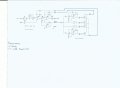
Hello,Oh yes H(s) is the BP transfer function, I forgot to mention that.
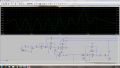
Yes i'll be using spice now, I downloaded it yesterday. So I'll see to rebuild it in Spice and i'll upload it later. Multisim gives you some wacky responses tbh...and they vary ALOT once you use different op-amps geeze (Even with virtual op-amps the response was wacky)
Woa this makes perfect sense, this what explains why a value 10K for R6 gives 6dB, its because of the (A+1). I'll expand out my transfer function some more and see if I can get this relationship:
G= ((AAAA*R23*R3+2*R1*R23+2*R1*R22)*R4+2*R1*R22*R23)/((AAAA*R22*R3+2*R1*R23+2*R1*R22)*R4+2*R1*R22*R23).
which was obtained by setting the 10R resistor to 0. Should this be done when simulating or in real life? To get the behaviour as close to the theoretical model as possible?
To understand the circuit theoretically it is best to set the 10 ohm resistors to zero. The 10 ohm resistors force approximations in the theoretical operation and that just makes it harder to comprehend what is going on with the main theory of the circuit.
If you get the LT Spice version ready i'd be happy to look at that too.
[UPDATE]
I see now the 10 ohm resistors are not about protecting the inputs of the op amps. They apparently set a limit on the range of the pot setting. The designer must have thought that it would be better to limit the gain slightly. However, 10 ohms does not do enough when combined with the tolerance of the other resistors. I would think 100 ohms minimum. However, they may be completely unnecessary.
To deal with the 10 ohm (or 100 ohm) resistors in theory, we can simply add them to the value of the pot resistors in the equation. Thus instead of using 100k which divides in half as 50k and 50k at the center setting, we could use 100k+10+10 and that would divide in half as 50k+10 and 50k+10, which as we can see is very minimal and so should have very little effect.
Last edited: