Facebook
 Google
 GitHub
 Linkedin
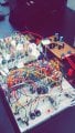
Built up 9/15 filters this week gone.
I don't have any equipment in the lab that I can bode plot with (I was referred to an audio analyzer, which I will try to use in one of the other labs).
So for now I just build a filter, then test it on the scope. So I send a sine wave into it whose frequency is that of the center frequency of the filter, then I increase the frequency and decrease it below that to ensure that the amplitude of the wave drops off. Which they are doing thus far. So that's my rough test to confirm that the filters are working as designed until I get actual bode plots to see the full response.
I predict that i'd finish the rest of this filters this week then construct this circuit

http://sound.whsites.net/project75.htm
Something I was wondering regarding this design that the author didn't really cover, was the input filter(Formed by C1 and R1), how do I go about choosing the right cutoff frequency? Is it supposed to be the frequency of my highest band? Also what purpose does R2 really serve?
I don't have any equipment in the lab that I can bode plot with (I was referred to an audio analyzer, which I will try to use in one of the other labs).
So for now I just build a filter, then test it on the scope. So I send a sine wave into it whose frequency is that of the center frequency of the filter, then I increase the frequency and decrease it below that to ensure that the amplitude of the wave drops off. Which they are doing thus far. So that's my rough test to confirm that the filters are working as designed until I get actual bode plots to see the full response.
I predict that i'd finish the rest of this filters this week then construct this circuit
http://sound.whsites.net/project75.htm
Something I was wondering regarding this design that the author didn't really cover, was the input filter(Formed by C1 and R1), how do I go about choosing the right cutoff frequency? Is it supposed to be the frequency of my highest band? Also what purpose does R2 really serve?