Help with building a Circuit

Thread Starter

bart796

Joined Aug 12, 2014
10
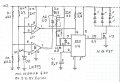
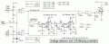
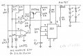
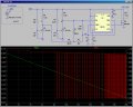
I am trying to build a low voltage circuit for a 12 volt battery. I have seen many but none do what exactly i want or i have not seen one that does through searching so maybe someone can point me in the right direction if one exists. The circuit i want should blink an LED strip at 11.1 volts. Thats the main idea i have. The second would be that at 11.1 it blinks every few seconds and then at say 10.5 it blinks rapidly. I have seen a few circuits that will turn an led on but my problem is the LEDS are always on in this particular project so that circuit is useless but maybe somehow could help me with a way to make it blink by perhaps turning a switch off and on at 11.1 or something. Thanks in advance and yes i did search before posting but i was unable to locate a specific circuit and yes i am a newbie at circuits but i am very good with electronics and have tons of experience soldering so building it will be zero problem i just need the wisdom on how to accomplish it! thanks!
 

Thread Starter

bart796

Joined Aug 12, 2014
10
Ok i have looked up the first part of what you said and came back with part number LM393. I am a total newb at circuits so I am not sure what to do with that but it is a starting point and i'll take to google and see if i can string some ideas together as to how this idea you have given would work! Maybe i can figure it out..probably not but ill give it a whirl!
 

MikeML

Joined Oct 2, 2009
5,444
Could you use a simple circuit that would normally just turn on a simple LED when the battery voltage drops where the simple LED is replaced with a self-blinking one like this?

Here is my favorite "turn on a LED when the voltage drops below x Volts" circuit. It is simple, and has a low parts count. Note the use of the TL431 precision voltage reference chip.

Unfortunately, when used this way, the TL431 anode is pulled (low) to ~2.1V when the input voltage V(i) is greater that the trip point. To guarantee that the LED indicator is off when the anode is low, I simply put two LEDs in series, so that the forward voltage of the two LEDs in-series prevents any current flow. When the TL431 turns off, the current through the 680Ω resistor R1 lights both LEDs. I normally mount one on the circuit board, and the other as a through-panel indicator lamp.

To get the blinking LED, just replace one of the two in the circuit above with the self-blinking kind from DigiKey. You have a choice of colors.

The simulation shows the current through the two LEDs I(D4) as the input voltage V(i) sweeps from 10V to 12V. The simulation shows what happens to the trip point at temperatures ranging from 0degC to 50degC in steps of 10degC.

To get a different trip voltage, play with R2. For two indicators with different trip points, build the circuit twice, and buy different color blinky LEDs.

If you are using this on a SLA, be advised that you are damaging the battery if you discharge it all the way to 11V.
 

Attachments

Last edited:

Thread Starter

bart796

Joined Aug 12, 2014
10
No i cannot replace the LEDs. The circuit is going to go on a RC airplane that i fly at night. It uses a 3 cell lipo battery and i want the entire LED setup to blink when my voltage hits 11.1. I have 39.5 feet of LEDS so its a very high MAH application i think they draw somewhere around 5000 mah an hour just for the LEDs. This is why i want the circuit to blink. I want it to cause all 39.5 feet to blink without pulsing the power to my RC motor at the same time.
 

MikeML

Joined Oct 2, 2009
5,444
So what you really want is circuit that turns your load (LEDs) on full when the voltage is above x Volts, pulses the load while the voltage is between x and y Volts, and turns off the load when the voltage is below y Volts?

Added: slow down the flash rate as the voltage sags from x to y Volts?

Note y < x...
 
Last edited:

Thread Starter

bart796

Joined Aug 12, 2014
10
Well i want the leds to be full on full output from basically 12.6 all the way to 11.2 once it hits 11.1 i would like them to flash say every few seconds. I would have to figure out how to isolate them from the motor and servos so i still maintain full control of the plane while the lights flash indicating i need to land asap.
 

shteii01

Joined Feb 19, 2010
4,644
I think I would use a little microcontroller board that has ADC.

My own limited experience is with Arduino. They make some little boards that don't take much space and there are clones that might be even smaller. Assuming the boards have 0-5 volts ADC, you can make a simple voltage divider where 12.6 volts goes into voltage divider, 5 volts comes out, feed the 5 volts to the ADC on the microcontroller board. Assuming 8 bit ADC, 5 volts is 255. So.
Battery is 12.6 volts, divider output is 5 volts, ADC outputs 255, LEDs are On.
Battery is 12.5 volts, divider output is 4.96 volts, ADC output is 253 LEDs are On.
.
.
.
Battery is 11.2 volts, divider output is 4.44 volts, ADC output is 226, LEDs are On.
Battery is 11.1 volts, divider output is 4.40 volts, ADC output is 224, software sees 224 and sends command to flashing circuit to flash LEDs.
 

Bernard

Joined Aug 7, 2008
5,784
This might do it if you do not mind discrete IC's. The MC1404U6 gives a stable 6.2 V ref, but in a pinch could use a 5 V to 8 V zener diode. V dividers R 1-4 can be pots. Slow blink about [ R7+R8]* C, fast blink just R8*C, & on time R9 * C.
The LED's are going to draw a large hunk of current so add as large of a power supply decoupling capacitor as you can tolerate- 1K uF or better.

Back to the drawing board, one "small" error-- with 555 reset , LED's always on.
 

Attachments

Last edited:

MikeML

Joined Oct 2, 2009
5,444
Great minds, and all that...

Here is my version. Low flash rate commences at ~11.5V, Fast flash rate about 11.2V.
Green trace is falling battery voltage V(cc) vs time (sped up). Red trace I(R9) is the ~5A through your string of LEDs...
 

Attachments

Last edited:

BMorse

Joined Sep 26, 2009
2,675
here is an example of a comparator setup, same concept except this monitors a 12 volt automobile type battery, but can easily adapted for what you want, everything past the outputs of the 4001N can be removed and replaced with an appropriate 555 timer circuit driving a mosfet to blink the led's.


R2 is where you would setup for 1st trip point, and R1 can be set for the second trip point.
 
Last edited:

MrSmoofy

Joined Jul 28, 2014
112
Side question here "39.5 feet of LEDS" you have an RC plane that you can fit 39.5 feet of LED's on :eek: Would love to see a video of that it must be huge.
 

MrSmoofy

Joined Jul 28, 2014
112
Probably wrapped around.
Hadn't thought of that. Still seems like a lot.

Most RC aircraft owners I know tend to want the aircraft as close to a replica of the plane it's designed after.

That said what about the standard anti colision lights all aircraft must have (red/green wing lights) and the strobes it must have for VFR at night and IFR (VFR = Visual Flight Rules, IFR = Instrument Flight Rules)

If your RC plane has these instead of adding more LED's what about doing something with these to indicate when the battery level is low. Maybe the strobe light is solid instead of strobe or the wing lights flash instead of solid or alternate flashing to get your attention.
 
Last edited:

Bernard

Joined Aug 7, 2008
5,784
All features OP requested, flash = 70 ms, slow pulse 4 s, fast pulse 1 s. Flash could be shorter and still be visable.
AC is analog coupler consisting of white LED facing light dependent resistor, > 2M off, < 1k on, in light tight package.
D1 = 1N4148
Breadboard tested, from AC to right.
U1-B needs to have pin 5 & 6 interchanged so that when battery is at 12 V, U3 is off.
 

Attachments

Last edited:

BMorse

Joined Sep 26, 2009
2,675
All features OP requested, flash = 70 ms, slow pulse 4 s, fast pulse 1 s. Flash could be shorter and still be visable.
AC is analog coupler consisting of white LED facing light dependent resistor, > 2M off, < 1k on, in light tight package.
D1 = 1N4148
Breadboard tested.

that looks great Bernard :)
 

Thread Starter

bart796

Joined Aug 12, 2014
10
It has a 6 foot wing span and is a glider and thanks for all the help guys i will look at these ideas and see if any will do what i need!
 

ScottWang

Joined Aug 23, 2012
7,397
The attached circuit almost completed, but I left the R1~R4 for you.

If you want to change the blinking timer then you can change the R7 and C1, if you want to change the blinking time then you can change the R9 and C3.

The control circuit should use another battery to detecting all the time, but the current is not that much.

I'm not sure the circuit match your need or not, but I already tried to solve the puzzle from your posts.

If any one found any error, please just point out, thanks.


Attachments

Top