Facebook
 Google
 GitHub
 Linkedin
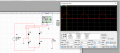
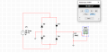
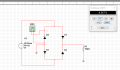
My problem involves a full wave bridge rectifier with no capacitor or transformer attached to a 20Vrms 60Hz AC source.
I am trying to find Peak Inverse Voltage (PIV) across the diodes alongside DC voltage across the load. In this case, the problem asks that I assume that the diodes are not ideal and in forward bias, thus resulting in a 0.7V voltage drop across each one.
Here is my work so far.
Vout = (20 * 1.414) - 1.4 = 28.28 - 1.4 = 26.88V
V(DC) across the load = (2*(Vout)) / pi = (2*26.88) / pi = 53.76 / pi = 17.11V
PIV = Vin - 0.7 = Vout + 0.7 = 26.88V + 0.7V = 27.58V
However, these results do not match up with the simulations that I've done with an equivalent circuit, with virtual diodes at 25 degrees celsius and all other configurations set to their defaults.
I would like to know what I am missing in regards to my calculations above.
Thank you in advance.
Attachments
-
 17.1 KB Views: 43
 -
 16.8 KB Views: 44