Can anyone help me get a simple op amp integrator to function?

Thread Starter

rowbo764

Joined Feb 5, 2025
11
Hello,
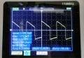
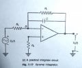
I am new to electronics. I tried using a generic integrator circuit I found on the Internet (attached circuit) to integrate a square wave input signal generated by a 555 time. I read lots about the theory of integrators and how practical circuits diverge from ideal op amps. Although I followed the rules, I just cannot get any ramp output at all. In fact the output (using LM358 op amp) is pretty much the same as the 555 input. I used a LM358 simply because my dual rail power supply had bust and LM358 can be used with single supply. I will upload my breadboard circuit ( I know they are not ideal) and some oscilloscope waveforms frist the input from the 555 and then the output from the LM358. I only used one of the two op amps on the LM358. I used a 10Meg resistor in parallel with the capacitor and the resistors on the inverting and non-inverting op amp inputs were both 4.7K ohms. I tried lots of capacitor values but the output did not change much and was nothing like the ramp of a triangular output that was expected. I used the criteria that the period of the input signal to the integrator should be greater than or at least equal to the product of the capacitor and resistor values and that a good choice (I read) for the resistor value from the non-inverting input to ground should be equal to the parallel combination of the other two resistors ( and the effect then of the large 10Meg resistor in parallel (i.e reciprocal) becomes negligible in value so I used 4.7K ohms for both the resistors and the 10Meg across the capacitor. To meet the other aforementioned criterion I selected a capacitor value of 10pF, although as mentioned I varied that over a large range of values with little effect. I sometimes in error make incorrect breadboard connections but everything seems ok. I would be grateful for any suggestions what is going wrong with my design. Its very frustrating that many designs of integrators on the Internet claim to work but the ones I have tried do not. I must be doing something very wrong.
Thank you for any help.
 

Attachments

crutschow

Joined Mar 14, 2008
38,400
As a newbie you need to know that the language of electronic is schematics, so can't help you much without an exact schematic of the circuit your breadboarded.
I don't have the patience on inclination to try to figure out your circuit from your verbal description or a picture of that breadboard.

It may be that the integrator needs a longer time-constant to properly integrate the square-wave frequency of the 555 but that's only a WAG.
 
Last edited:

Thread Starter

rowbo764

Joined Feb 5, 2025
11
As a newbie you need to know that the language of electronic is schematics, so can't help you much without an exact schematic of the circuit your breadboarded.
I don't have the patience on inclination to try to figure out your circuit from your verbal description or a picture of that breadboard.

It may be that the integrator needs a longer time-constant to properly integrate the square-wave frequency of the 555 but that's only a WAG.
Hello, Thankyou for reading my post. I apologise for my inadequacies in communication. I have drawn out a circuit schemmatic and would very much welcome your comments as an expert on circuits and electronics. I always look at the comments you have kindly given to other people.
Robert
 

Attachments

Thread Starter

rowbo764

Joined Feb 5, 2025
11
And try a capacitor of about 20nF.
Thanks for your input. Tying the non inverting (pin 3) of LM358 to half the supply voltage (2.5V) and changing capacitor to 33nF gave a significant improvement. How could I obtain just a triangle wave from this circuit? I feel I am nearly there. Why did the potential divider (2.5V) on pin 3 help?
 

Attachments

Thread Starter

rowbo764

Joined Feb 5, 2025
11
Your output waveform looks like there is a resistor in series with the capacitor of about 1.5kΩ.
Oh dear I thought I was getting somewhere. Have you got any suggestions? You see the circuits published for op amp integrators are essential the same as mine and what you are saying is that my circuit is not an integrator at all. Perhaps you know of a better practical op amp integrator that you have built and which you can vouch for. That would be helpful. Thank you for your time.
 

crutschow

Joined Mar 14, 2008
38,400
Oh dear I thought I was getting somewhere. Have you got any suggestions? You see the circuits published for op amp integrators are essential the same as mine and what you are saying is that my circuit is not an integrator at all. Perhaps you know of a better practical op amp integrator that you have built and which you can vouch for. That would be helpful. Thank you for your time.
Your schematic looks okay.
It just doesn't match the output you are seeing so I suspect an error in your wiring.
Have you double-checked it?
 

sparky 1

Joined Nov 3, 2018
1,218
A simple example of constructing an op amp integrator step by step.
The video shows a lab exersize where imperfection can be seen.
The lab instructor might check the values of the parts and they are not perfect
and he understands where the wires go. The function generator works, it has a fine adjustment
but the frequency, amplitude ok, not perfect. (555 adjusted to 2V on oscilloscope looks like below)
Lastly the math is just a few easy get er done equations.
For the given parts the equation RC timing is ok and the oscilloscope timing settings match.
The video shows what happens when you mess with the oscilloscope. Channel A and B are equal in proportional

The instructor knows to leave good enough alone. He got the equation to work sort of.
It can be trimmed out better if you get it in spec first.

When you combine a square and a sawtooth you get a trapazoidal wave using a filter on the output. Wave shaping by combining.
There can be a jump voltage when trying to implement a comparator, this is typically a sharp rise in the leading edge.
Whereas the regular op amp produces a slow rise which is shown as a symmetrical triangle


Qualty of square to triangle converter when improving the filter too much.

 
Last edited:

AlbertHall

Joined Jun 4, 2014
12,623

Thread Starter

rowbo764

Joined Feb 5, 2025
11
A simple example of constructing an op amp integrator step by step.
The video shows a lab exersize where imperfection can be seen.
The lab instructor might check the values of the parts and they are not perfect
and he understands where the wires go. The function generator works, it has a fine adjustment
but the frequency, amplitude ok, not perfect. Lastly the math is just a few easy get er done equations.
For the given parts the equation RC timing is ok and the oscilloscope timing settings match.
The video shows what happens when you mess with the oscilloscope. Channel A and B proportional
The instructor knows to leave good enough alone. He got the equation to work sort of.
It can be trimmed out better if you get it in spec first and not verse visa.

Thanks. I am subscribed to his youtube channel but he not spot it. There are so many seemingly simple integrator circuit designs online but despite what is said , many just don't work on a breadboard and yet there are so few components you wonder what can be wrong.
 

Thread Starter

rowbo764

Joined Feb 5, 2025
11
This is the usual result of AC coupling but the slope seems rather steep for the usual values in the scope.
When the input changes, the screen shows the change but then the input capacitor discharges through the scope input and the screen shows the voltage sagging.

See: https://electronics.stackexchange.c...w-frequencies-high-pass-filtering-ac-coupling
Your link was interesting. I am only using a cheap £50 Chinese make handheld scope but it does have coaxial connector with earthing strap and I check the setting AC, DC and also on the probe itself, having that set to X1 since the frequency of my input signal is in the audio range. Thank you again for your comments.
 

Papabravo

Joined Feb 24, 2006
22,065
A pure integrator has a couple of problems, not the least of which is a very high gain at frequencies below 1Hz. The "lossy" integrator has a defined gain at DC and low frequencies and a single pole roll-off above the corner frequency. The frequency of the input square wave needs to be the dominant pole frequency, depending on C1 & R2, times a factor of five or so. The segments of the output are not linear; they are exponential curves with a low radius of curvature. Plotting the derivative of the output demonstrates the non-linearity of this technique.

The blips at the min and max of the output are due to the discontinuous derivative of the input waveform. The is a good deal of distortion at those points due to the rapid rise and fall times.

The LM358 is OK for many applications but has substantial limitations in this application.

There are better techniques for generating triangle and sawtooth waveforms.

1742498078029.png
 

Attachments

Thread Starter

rowbo764

Joined Feb 5, 2025
11
A pure integrator has a couple of problems, not the least of which is a very high gain at frequencies below 1Hz. The "lossy" integrator has a defined gain at DC and low frequencies and a single pole roll-off above the corner frequency. The frequency of the input square wave needs to be the dominant pole frequency, depending on C1 & R2, times a factor of five or so. The segments of the output are not linear; they are exponential curves with a low radius of curvature. Plotting the derivative of the output demonstrates the non-linearity of this technique.

The blips at the min and max of the output are due to the discontinuous derivative of the input waveform. The is a good deal of distortion at those points due to the rapid rise and fall times.

The LM358 is OK for many applications but has substantial limitations in this application.

There are better techniques for generating triangle and sawtooth waveforms.

View attachment 345030
Thanks for that. Its very interesting. The only reason I used a LM358 was because my dual rail power supply had died so I needed an op amp that would work from a single supply. There are not that many around but I had a 358. Is the red plot showing the derivative of the green output waveform?
 
Top