Help to find angular cutoff frequency from phasediagram

Thread Starter

Dallaaas

Joined May 11, 2024
21
Hi,
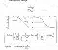
From this phasediagram Im reading the angular cutoff frequency to:
3kHz hence -45 degress
30kHz hence -135 degress
But last one is a bit tricky.
Phaseangle is aprox -205
And -tan^-1=(1) + (300/30) +(300/3) = 45+84+89=-218 degres.
Because phase is more then -180 we know that it´s atleast 3 angular cutoff frequency.
1736424325836.png
 

Attachments

LvW

Joined Jun 13, 2013
1,994
As it seems, your drawings show a 3rd-order lowpass. But, perhaps, it is a 4th-oder with a zero around 300 Hz (see the slope of the phase function)
However, such a lowpass has one single cutoff-frequency only - and it is a common agreement that this frequency is at a point where the gain is as low as (Amax-3dB). Hence, it is a frequency of app. 3...4 kHz.

However, such a 3rd-order lowpass has three pole frequencies .
But they are NOT at frequencies with phase angles of -45, -135 or -180 deg (as you seem to assume).

* Only a first oder lowpass has a 3db-cutoff at -45 deg.
* A 2nd-oder lowpass has a phase shift of -90deg at the pole frequency only. The cutoff-frequency depends on the quality factor.
 

Thread Starter

Dallaaas

Joined May 11, 2024
21
I was assuming (we have only had these kinds of filter in previous questions).
And on filter can contribute with -90 degrees. Therefore, it must be atleast three of these since we are exceeding -180 degrees it´s going to be 3 cut off frequencys. If you look at 30kHz, we are at -135 degrees meaning, when has been active for more then one decade and one is getting active and we get -45-90 =-135.

I´m I completely wrong here?
 

Attachments

Papabravo

Joined Feb 24, 2006
22,058
The diagram shown in your post #3 is for a 1st order pole only. This pole will be located on the negative real axis and has a Q of exactly 0.5. A 1st order pole cannot exhibit gain or oscillatory behavior.

A 2nd order section has a quadratic function in the denominator of the transfer function. As you know it may have a pair of real roots, which lie on the negative real axis, and they will behave as cascaded 1st order sections with the same properties as any other 1st order section. The roots of a quadratic function may also be a complex conjugate pair. The effect is to increase the rolloff in the transition band from 20 dB/decade to 40 dB/decade, and the phase shift increases to 90° at the -3 dB point.

All higher order filters can be decomposed into a cascade of 2nd order sections for even orders, or a 1st order section followed by a cascade of 2nd order section.
 

Thread Starter

Dallaaas

Joined May 11, 2024
21
Yes but if you combine three of 1st order pole they can oscillate, depending?
Earlier when we worked on this kinda problems we always had these kinda filter combined. But in this case that´s not whats happening if Im correct.

The question was to compensate with -1 dominating filter (picture 2) to get 45 degrees phase margin at 0dB.
The answer to this was to place the new filter at 200Hz. If we place it at 200Hz the -1 dominating filter has only contribute for 2 decades when the phase angle is -135 degrees and therefor the raw gain will be 20dB and not 0dB as for whats asked in the question.
 

LvW

Joined Jun 13, 2013
1,994
The roots of a quadratic function may also be a complex conjugate pair. The effect is to increase the rolloff in the transition band from 20 dB/decade to 40 dB/decade, and the phase shift increases to 90° at the -3 dB point.
That is not quite correct.
As I wrote - a 2nd-order lowpass has a phase shift of -90deg at the pole frequency wp only.
Only in case of a maximally flat magnitude response (Butterworth approximation) the pole frequency wp is identical with wc (3dB-cutoff).
For all other responses (Bessel, Chebysheff,..) the pole frequency wp is NOT identical with wc (3dB-cutoff).


And on filter can contribute with -90 degrees. Therefore, it must be atleast three of these since we are exceeding -180 degrees it´s going to be 3 cut off frequencys. If you look at 30kHz, we are at -135 degrees meaning, when has been active for more then one decade and one is getting active and we get -45-90 =-135.
I´m I completely wrong here?
Why do you speak about "3 cut off frequencys" ?
I see a third-order or fourth-order lowpass response with one cut-off frequency only.
 

Thread Starter

Dallaaas

Joined May 11, 2024
21
Why do you speak about "3 cut off frequencys" ?
I see a third-order or fourth-order lowpass response with one cut-off frequency only.
So what we have in the book and what we had on all of our exames before we hade mulitple first-order? filters stacked after each other on different frequency, so Im not well known with third or fourth-order filter with only one cut-off frequency and Im trying to understand it and how it works.

The question was to compensate with -1 dominating filter (picture 2) to get 45 degrees phase margin at 0dB.
The answer to this was to place the new filter at 200Hz. If we place it at 200Hz the -1 dominating filter has only contribute for 2 decades when the phase angle is -135 degrees and therefor the raw gain will be 20dB and not 0dB as for what´s asked in the question.
 

LvW

Joined Jun 13, 2013
1,994
So what we have in the book and what we had on all of our exames before we hade mulitple first-order? filters stacked after each other on different frequency,
In order to follow your explanation (and to fully understand your problem description) it is necessary to tell us if the various 1st-oder sections you have mentioned are isolated to each other (buffer amplifiers) or not.
Without isolating buffer stages, each RC section is loaded by the following sections and it makes really no sense to treat each section separately.
 

Thread Starter

Dallaaas

Joined May 11, 2024
21
An amplifier with raw gain, Av0A_{v0}Av0, as a function of frequency according to the diagram below, is voltage-voltage feedback-coupled with a resistive feedback factor β\betaβ. The amplifier can be assumed to have high input impedance and low output impedance.
c) Compensate the amplifier using the method with a dominant -1 breakpoint such that a phase margin of 45° down to 0 dB gain is achieved. Present the amplifier's characteristics after compensation in a Bode diagram. (1 point)

This is all that´s given.

1736439306521.png
 

LvW

Joined Jun 13, 2013
1,994
An amplifier with raw gain, Av0A_{v0}Av0, as a function of frequency according to the diagram below, is voltage-voltage feedback-coupled with a resistive feedback factor β\betaβ. The amplifier can be assumed to have high input impedance and low output impedance.
c) Compensate the amplifier using the method with a dominant -1 breakpoint such that a phase margin of 45° down to 0 dB gain is achieved. Present the amplifier's characteristics after compensation in a Bode diagram. (1 point)

This is all that´s given.
That is a complete other story than given in the 1st post.
Phase margin can be found/recalculated/modified based on the loop gain only.
As far as I can understand your text, the given Bode Diagram applies to a closed-loop gain, right?
 

Thread Starter

Dallaaas

Joined May 11, 2024
21
That is a complete other story than given in the 1st post.
Phase margin can be found/recalculated/modified based on the loop gain only.
As far as I can understand your text, the given Bode Diagram applies to a closed-loop gain, right?
I´m pretty sure its the open loop gain. As saying in the question, task is compensate the amplifer with a dominant -1 breakpoint.
I can´t figure out how that´s possible if you apply that point at 200Hz.
 

LvW

Joined Jun 13, 2013
1,994
I´m pretty sure its the open loop gain. As saying in the question, task is compensate the amplifer with a dominant -1 breakpoint.
I can´t figure out how that´s possible if you apply that point at 200Hz.
Surprisingly - now its a complete other problem description as given in your first post.
Nevertheless:
* Question: Is the shown diagram based on real measurements?
If yes, the phase diagram should start at -180deg (negative feedback for low frequencies incl. DC.)

* When the Bode diagram gives the loop gain you must apply the established method for finding the phase margin.
Do you know how this margin can be found?
Do you know something about methods to improve this margin?
 

Thread Starter

Dallaaas

Joined May 11, 2024
21
Surprisingly - now its a complete other problem description as given in your first post.
Nevertheless:
* Question: Is the shown diagram based on real measurements?
I cant answer I did not make the exame.
If yes, the phase diagram should start at -180deg (negative feedback for low frequencies incl. DC.)

* When the Bode diagram gives the loop gain you must apply the established method for finding the phase margin.
Do you know how this margin can be found?
Not sure. Are we talking maximum -180deg margin at 0dB then yes.

Do you know something about methods to improve this margin?
Yes, and for this particular question, its mandatory to use new -1/decade with a total phaseshift of -90deg.
 
Last edited by a moderator:

LvW

Joined Jun 13, 2013
1,994
Yes, and for this particular question, its mandatory to use new -1/decade with a total phaseshift of -90deg.
No - it is not mandatory.
That would be only one of several alternatives for improving the stability margin and - let me add - it is not the best method.
However, for corresponding recommendations it is mandatory to see the circuit diagram for the whole closed-loop.
 

Thread Starter

Dallaaas

Joined May 11, 2024
21
No - it is not mandatory.
That would be only one of several alternatives for improving the stability margin and - let me add - it is not the best method.
However, for corresponding recommendations it is mandatory to see the circuit diagram for the whole closed-loop.
We are not given a circuit diagram. And in the question in the exame it stats:
" Compensate the amplifier using the method with a dominant -1 breakpoint such that a phase margin of 45° down to 0 dB gain is achieved"
 

LvW

Joined Jun 13, 2013
1,994
We are not given a circuit diagram. And in the question in the exame it stats:
" Compensate the amplifier using the method with a dominant -1 breakpoint such that a phase margin of 45° down to 0 dB gain is achieved"
When I have the task to modify the frequency response of an amplifier I must know how this amplifier looks like.
Only in this case I can find a suitable location for connecting/inserting a corresponding compensation circuitry - as a precondition for finding the parts values.
Example: If it is an operational amplifier I can connect a suitable R-C compensation combination between both opamp inputs (external frequency compensation).

By the way: The wording "...method with a dominant -1 breakpoint such that a phase margin of 45° down to 0 dB gain is achieved." sounds a bit confusing (uncommon) to me.
What is a "-1 breakpoint" and what means "down to 0 db"?
I think the term "phase margin" is clearly defined.
 

Thread Starter

Dallaaas

Joined May 11, 2024
21
When I have the task to modify the frequency response of an amplifier I must know how this amplifier looks like.
Only in this case I can find a suitable location for connecting/inserting a corresponding compensation circuitry - as a precondition for finding the parts values.
Example: If it is an operational amplifier I can connect a suitable R-C compensation combination between both opamp inputs (external frequency compensation).
Yeah I understand that. But in this given question it´s not an option. I don´t know how the examinator has come up with cut off frequency at 200Hz to achive a -135deg at 0dB - hence what Im seraching to get help with here.
 

LvW

Joined Jun 13, 2013
1,994
Yeah I understand that. But in this given question it´s not an option. I don´t know how the examinator has come up with cut off frequency at 200Hz to achive a -135deg at 0dB - hence what Im seraching to get help with here.
I must admit - I also do not know how he came up with 200 Hz.

When the first pole frequency would be at 200 Hz a first order response (with 20dB/Dek) would cross the 0-dB line at app 200 kHz (60 dB gain=3 decades). For a phase margin of 45 deg. the 2nd. pole frequency must appear at this frequency (not earlier).
Howver, a look at your diagram shows that this is - by far - not the case.
Hence, the first pole (created by compensation) must be much lower than 200Hz (some Hz only).

It should be mentioned that the above considerations are based on my present understanding of the task:
Add an additional pole at low frequecies (first order compensation) wthout changing the remaining circuitry and the corresponding poles of the circuit.
 
Last edited:

Thread Starter

Dallaaas

Joined May 11, 2024
21
I must admit - I also do not know how he came up with 200 Hz.

When the first pole frequency would be at 200 Hz a first order response (with 20dB/Dek) would cross the 0-dB line at app 200 kHz (60 dB gain=3 decades). For a phase margin of 45 deg. the 2nd. pole frequency must appear at this frequency (not earlier).
Howver, a look at your diagram shows that this is - by far - not the case.
Hence, the first pole (created by compensation) must be much lower than 200Hz (some Hz only).

It should be mentioned that the above considerations are based on my present understanding of the task:
Add an additional pole at low frequecies (first order compensation) wthout changing the remaining circuitry and the corresponding poles of the circuit.
Exactly my thought.
I tried to get an answer out of him but he usually don´t respond or not in detail. I will wait and see.
 
Top