Help separating stacked PCB's using press fit connectors

Thread Starter

Blacknd

Joined Nov 1, 2019
6
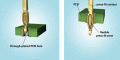
I'm trying to figure out how to separate 2 PCB's held together by solder less pins without destroying anything.
I need to separate these to get to some bad solder joints. This is a $1000 part that I know I can fix, if only I can access the points.
Are there special tools to pull these pins from the board? I'm assuming the pins are solid and are connected on each board. I've tried pulling them apart, but was afraid of breaking it. Thought of making a tool to try and pry them up, but again I'm afraid of destroying it.
My last though was to just saw the header in half and solder a new one on when I put it back together. I don't want to do this, but I'm beginning to think I'll have to.
Any advice would be greatly appreciated.

On a side note. Why the heck would a car manufacturer build headlight relays into the computer.... Basically my headlights stay on all the time. I took off the casing to the body control module and hooked it back to the car. I can LIGHTLY squeeze the relays and everything works as it should.
 

jpanhalt

Joined Jan 18, 2008
11,087
If you want to remove the pins from the board, I would use a piece of thin-wall steel tubing (usually stainless) that will fit over the square tips and be small enough so the tabs are compressed enough to disengage from the board. Unfortunately, you need to do that simultaneously to each pin as multiple pins hold each connector. That calls for a lot of work (e.g., the same number of extraction tools as pins) or some machining, e.g, a plate with properly spaced holes of the right diameter. A special tool is probably made for doing that.

If you can find those connectors, the easiest approach would be to use side cutters and cut the protruding pins so they can be removed.

It is not clear to me how the black connectors fit together. Are you sure they cannot just be separated?
 

SLK001

Joined Nov 29, 2011
1,549
Stick a small blade screwdriver under the edge of the connector and lift it a little. Shift the position of the screwdriver and do it again. Repeat this until you can simply pull the boards apart. Don't try to do it in one "lift" - there is enough retention force to break the board. It's like the death of a thousand cuts, or the separation of a thousand lifts.
 

jpanhalt

Joined Jan 18, 2008
11,087
@Blacknd
For clarity, is this what you want to remove?
1572675101693.png
What I see is that the wings (retention fingers) of the pins overlap the edges of a plated through hole. It's kind of like the retaining fingers of a Molex connector. In my experience with Molex*, if you use brute force (e.g., a screw driver wedge) to pull them through without compressing the retention fingers you will run the risk of damaging the board. Worse case, you will pop the plating from the hole and lift a trace. That could be a disaster if it is a multi-layer board (>2 layers).

As already mentioned, my fist choice, assuming you can get replacement connectors, is to clip the tips off. The retention fingers can be removed by doing that, and the boards can be separated. If you cannot get new connectors/pins, then you need to compress them before removal. Maybe you can do just 2 or 4 at a time; it's hard to tell how flexible the thing will be. If you press the connector toward the board, some of the tension on the retention fingers will be relieved, which should make them easier to compress.

*Brute force without compressing the retention fingers always damages the connector and/or contact.
 

Thread Starter

Blacknd

Joined Nov 1, 2019
6
@Blacknd
For clarity, is this what you want to remove?
View attachment 190439
What I see is that the wings (retention fingers) of the pins overlap the edges of a plated through hole. It's kind of like the retaining fingers of a Molex connector. In my experience with Molex*, if you use brute force (e.g., a screw driver wedge) to pull them through without compressing the retention fingers you will run the risk of damaging the board. Worse case, you will pop the plating from the hole and lift a trace. That could be a disaster if it is a multi-layer board (>2 layers).

As already mentioned, my fist choice, assuming you can get replacement connectors, is to clip the tips off. The retention fingers can be removed by doing that, and the boards can be separated. If you cannot get new connectors/pins, then you need to compress them before removal. Maybe you can do just 2 or 4 at a time; it's hard to tell how flexible the thing will be. If you press the connector toward the board, some of the tension on the retention fingers will be relieved, which should make them easier to compress.

*Brute force without compressing the retention fingers always damages the connector and/or contact.

yes, those are the connectors i'm trying to remove. I thought they had small barbs on them as well, but i really don't think they do. Any literature i find on these type of connectors, they all seem to have this basic design.
I have thought there is possibly a small amount of solder fusing the pin and the pad, though they should be solderless from everything i'm reading.

I'm to the point i'm just going to cut the tips and resolder to put it back together. I'm still worried its going to be a pain to separate since all the retention force is in the hole. I tried to squeeze the pins and pry apart last night, but i didn't have a very good pry tool and there still seemed to be a lot of retention force. I will grab or make something today at work and try again before I go cutting anything.

one other thing that worries me if i were to cut the pins. I'm going to loose some structural integrity of the boards.
The board will fit into a case to protect it, but there are clips on each of the wiring harness connectors that will put a sight pulling pressure between the 2 boards. If that makes sense.... I doubt it would be enough to hurt anything, but i could see it eventually being a problem.
 

Attachments

jpanhalt

Joined Jan 18, 2008
11,087
That press-fit contact picture helps. I think cutting the tips off will reduce pressure considerably, I use McMaster Carr for thin-wall SS tubing (https://www.mcmaster.com/stainless-steel-tubing ), which is sometimes called hypodermic needle tubing.

If you have time for this repair, I would give compressing the pins a try. A 0.0353" ID will fit over a 0.025" square pin. You want the smallest OD possible (e.g., McM-Carr # 5560k49). You may find some extra-extra thin wall stuff that is even smaller OD.

If it is totally friction fit, a penetrating lubricant might help, but then it will need a good cleaning.
 

Thread Starter

Blacknd

Joined Nov 1, 2019
6
That press-fit contact picture helps. I think cutting the tips off will reduce pressure considerably, I use McMaster Carr for thin-wall SS tubing (https://www.mcmaster.com/stainless-steel-tubing ), which is sometimes called hypodermic needle tubing.

If you have time for this repair, I would give compressing the pins a try. A 0.0353" ID will fit over a 0.025" square pin. You want the smallest OD possible (e.g., McM-Carr # 5560k49). You may find some extra-extra thin wall stuff that is even smaller OD.

If it is totally friction fit, a penetrating lubricant might help, but then it will need a good cleaning.
I will see if i can dig up some tubing. My wife is a home health nurse, so she has a stock pile of needles in her car and maybe i can modify one to work. I'm also going to modify a set of needle nose pliers to have on hand in case i dont have a tube that will work.

I've tried to make a long solder tip to reach what i need to, but i just cant get a good joint doing it this way and i think at this point I need to desolder and clean them up.
 

Thread Starter

Blacknd

Joined Nov 1, 2019
6
So looking at this thing more, i'm beginning to wonder if i should just remove this connector and not separate the boards at all1256753327.jpg. the connector has the same pins, only slightly bigger. Once it's removed, i think i would have plenty of access to resolder what i need to.
 

shortbus

Joined Sep 30, 2009
10,045
Seeing the last picture, is it those press fit pins or the plastic standoffs that are the real problem? Some of those do have wings that need to be compressed to separate the boards.
 

Thread Starter

Blacknd

Joined Nov 1, 2019
6
Seeing the last picture, is it those press fit pins or the plastic standoffs that are the real problem? Some of those do have wings that need to be compressed to separate the boards.

i believe its just the pins. correct me if i'm wrong, but isn't the plastic stand off just for alignment purposes?
here is a pic of the black plastic harness connector. I dont see any "wings" or barbs that would be holding it in place.
 

Attachments

jpanhalt

Joined Jan 18, 2008
11,087
Much clearer picture. It seems to be just friction as you said in your earlier post. They could be pretty tight. Pressure would still be my preferred way to pulling, as it is more controlled should one suddenly let go. Prying is about the same, but yo have tried that. Penetrating solvent?

Are you sure you cannot get a replacement plug? If that is not possible, I like the idea of removing the plastic shroud (if possible), then remove one pin at a time.
 

SLK001

Joined Nov 29, 2011
1,549
What's holding the boards together is the retention force of the pins inside the connectors, not the pins thru the board. If you pull the pins out, you will most likely have to replace the board.
 

shortbus

Joined Sep 30, 2009
10,045
correct me if i'm wrong, but isn't the plastic stand off just for alignment purposes?
Not that the black plastic stand offs on each side of the pins your talking about. See how they have little wings that keep the boards from separating? Any that I've taken apart needed those squeezed to get the boards apart.
1572730000604.png
 
Top