Help redimensioning resistor values?

Thread Starter

DonutChan

Joined Mar 3, 2019
33
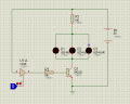
I have a working little circuit, the logicstate is supposedly coming out of a microcontroller. But it doesn't serve the purpose of the project i'm working on yet, so i'd like some help. I want to add 6 other LED's but i'm not certain how the calculation is done..
 

Attachments

djsfantasi

Joined Apr 11, 2010
9,163
The question is, with the added current of the additional LEDs, is the current on the transistor base sufficient

You didn’t as this, but the original LED wiring is, if not wrong, unreliable.
 

Analog Ground

Joined Apr 24, 2019
460
Probably related to reply from djsfantasi ("unreliable"). Not a good idea to directly parallel the LEDs off one resistor. They will not share current equally. It is only a question of how unequally. Give each LED it's own 100 ohm resistor.

The 2N2222 will have at least a current gain of 100 at your total current of around 100 mA. So, the transistor base should get at least 1mA from the logic output. This makes the 10K ohms a little large. Generally, drop this down to what the 74126 can drive in the high state and overdrive the transistor. I recall the 74126 can supply quite a bit in the high state. You pulled the Enable low which is a good thing.
 

AnalogKid

Joined Aug 1, 2013
11,041
Another problem is that the 74126 is a tri-state buffer. When the uC turns it "off", the Q1 base is left floating. While the LEDs do turn off, this is not a good way to drive the transistor. If you are stuck with the 126, add a 100K resistor from the Q1 base to GND. This will help it turn off faster and more reliably. and prevent false LED flickering in the presence of strong EMI.

As above, the way you are driving the LED group is not good. But if you are happy with it, then your second schematic is still has a problem. Assuming that the LED forward voltage Vf is approx. 3 V, then each three-LED group shares 20 mA. Three groups equals 60 mA, way less than what a 2N2222 can handle as a saturated switch; so far, ok. BUT, the 126 absolute max output current is only 2.6 mA, and the output voltage at that current is only 2.4 V, this works out to R3 being 692 ohms, not 10K. To protect the gate's output stage, round that up to the next highest value, 750 ohms (5%) or 698 ohms (1%).

The rule of thumb for solid saturation is that the ratio of collector current to base current should be no more than 10:1. Nice round number, but that rule came from the 1950's when transistors were not what they are today. I routinely recommend 20:1 as ok for parts like the 2N2222. However, with the base resistor change, your circuit is running at 25:1, on the edge of reliable performance. Consider changing Q1 to a MOSFET like the 2N7000/7002.

Read the datasheets.

ak
 

dl324

Joined Mar 30, 2015
16,917
I want to add 6 other LED's but i'm not certain how the calculation is done.
As others have mentioned, it's considered a poor design practice to put LEDs in parallel without each having it's own resistor.

Unless the LEDs have matched forward voltages (apparently some manufacturers sort by forward voltage), they may not have uniform brightness. You also risk a cascading failure.

You'll find cheap LED flashlights that put multiple LEDs in parallel, but they don't care if it fails. They also don't care if you buy more than one from them.
 

Wuerstchenhund

Joined Aug 31, 2017
189
Does anyone read the sticky at the top of this forum?
No, why should they, clearly some people give a shit where they post their question, with no consideration if its the right group or not :(

Frankly, if someone can't understand that "Test & Measurement Forum" does *not* include basic electronics stuff like sizing resistors for LEDs then I'd question if electronics is the right hobby (I'd suggest "painting by numbers" instead).

Pathetic, really.
 

ebeowulf17

Joined Aug 12, 2014
3,307
No, why should they, clearly some people give a shit where they post their question, with no consideration if its the right group or not :(

Frankly, if someone can't understand that "Test & Measurement Forum" does *not* include basic electronics stuff like sizing resistors for LEDs then I'd question if electronics is the right hobby (I'd suggest "painting by numbers" instead).

Pathetic, really.
I understand the accumulated frustration around issues like this, but wouldn't it be more productive (and polite) to directly address the thread starter and let them know how things are supposed to work here, instead of using passive aggressive hints?

I suppose if you've already dealt with this specific person and tried to tell them in the past, I would understand your reaction, but if this is a new user and first offense, couldn't we start with a friendly nudge in the right direction?
 

Audioguru

Joined Dec 20, 2007
11,248
The 2N2222 will have at least a current gain of 100 at your total current of around 100 mA. So, the transistor base should get at least 1mA from the logic output.
Absolutely not! To make the transistor turn on fully then it must saturate. Current gain is used when it is a linear amplifier with plenty of collector to emitter voltage so it is NOT saturated. The datasheet shows it saturates pretty well when its base current is 1/10th its collector current. Then a base current of 6mA is needed.
The output voltage of an (old) 74126 is only about 2.5V so the series base resistor should be (2.5V - 0.7V)/6mA= 300 ohms.

I agree that LEDs in parallel probably will not have the same forward voltage therefore will have different currents and different brightnesses.
 

Wolframore

Joined Jan 21, 2019
2,610
Why not use a mosfet? It uses less current and since you’re saturating anyhow why a transistor? And I won’t repeat what the others have correctly stated. Give each led its own resistor.
 

Audioguru

Joined Dec 20, 2007
11,248
I must have been looking at the datasheet for the 74HC126
With a 5V supply, the output of the old 74126 goes as high as about 2.5V at about 6mA. Kinda weak.
With a 5V supply, the output of the 74HC126 goes as high as 5V with a low current or to about 4V with a 35mA load. Very strong.
 
Top