Help Please with circuit repair (boat auto-pilot, TR-1).

Status
Not open for further replies.

debe

Joined Sep 21, 2010
1,419
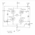
This is a circuit for motor reversing in an Auto pilot, May be of some help. The 12V rail does need some sort of fusing, preferably lower than what the copper tracks can handle. If a fault develops in the H bridge it will blow copper tracks like in your picture. It only takes one of the Mosfets to short for destruction to ocur. For each motor direction you need diagonaly oposite FETs to turn on.
 

Attachments

debe

Joined Sep 21, 2010
1,419
There will be 2 x P chanel & 2 x N chanel FETS in the circuit so make sure you have selected the right type for any replacements. In the circuit resistor 224 is used to sense Motor current, so when the motor went hard over the motor should have created a load big enough to shut it down. Thats how tiller pilots work to protect the swiching FETs.
 

Attachments

Thread Starter

AJ Peacock

Joined Aug 11, 2012
34
There will be 2 x P chanel & 2 x N chanel FETS in the circuit so make sure you have selected the right type for any replacements. In the circuit resistor 224 is used to sense Motor current, so when the motor went hard over the motor should have created a load big enough to shut it down. Thats how tiller pilots work to protect the swiching FETs.
The transistors on my board have lost all their markings. I chose an N-channel based solely on the MOSFET driver (MIC5016BWM) app notes I found online. I chose a IRFZ40.

Is there any way for me to make sure I've chosen wisely?

If I put an N-channel in the circuit and it is expecting a P-channel, will I do more damage? Or will it just fail to work?

The onboard fuse is 10A, I'll probably put a 2A in there for the smoke testing, is that a good idea?

Thanks,
Don
 
Last edited:

R!f@@

Joined Apr 2, 2009
10,007
The 2A will be too small to drive the motor. It will fail during a load test even if the circuit works properly.

If u replace N channel with a P. The P will turn on at power up even though the drive is inactive.

N channel gate needs a positive charge respective to source so at 0V it is inactive. Say u put a P. At 0V gate potential the source is postitive. Now u do the math.

Am I wrong here Sgt ?
 

Thread Starter

AJ Peacock

Joined Aug 11, 2012
34
The 2A will be too small to drive the motor. It will fail during a load test even if the circuit works properly.

If u replace N channel with a P. The P will turn on at power up even though the drive is inactive.

N channel gate needs a positive charge respective to source so at 0V it is inactive. Say u put a P. At 0V gate potential the source is postitive. Now u do the math.

Am I wrong here Sgt ?
So, it won't break anything? It just wont work. Correct?

The motor is a small pump, I don't know it's draw, it's probably 2" diameter and 6" tall. I think it's actually a pump for window washer fluid !


Thanks,
Don
 

Thread Starter

AJ Peacock

Joined Aug 11, 2012
34
This is a circuit for motor reversing in an Auto pilot, May be of some help. The 12V rail does need some sort of fusing, preferably lower than what the copper tracks can handle. If a fault develops in the H bridge it will blow copper tracks like in your picture. It only takes one of the Mosfets to short for destruction to ocur. For each motor direction you need diagonaly oposite FETs to turn on.
I'll add some more info that may help us out.

The end of the motor fits into the larger round hole in the board (doesn't touch, just fits there). This makes the Q09 transistor almost touch the body of the pump, in fact, there was plastic tape on the motor to further isolate the transistor from the pump. Also, the transistors were insulated from the flat metal heat sink with small plastic bushings.

When I opened up the pump/circuit box, the transistor (Q09) had shorted towards the pump motor (it's package had melted toward the pump), it had also melted the bushings that isolated it from the metal heat sink plate. So I guess a positive charge had to flow threw the transistor onto the outside of the pump?

Would that make it a P-channel? or am I really showing my NOOBy-NESS ??

Thanks,
Don
 

R!f@@

Joined Apr 2, 2009
10,007
N channel will work if gate is positive respective to source & vice versa for P.

Does that board use single ended supply or dual supplies
 

Thread Starter

AJ Peacock

Joined Aug 11, 2012
34
I received an additional board today. It was corroded due to water dunking. The transistors on this board have no markings either, but they look usable.

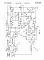
Also, I can see the traces really well on this board. The trace between Q9 and Q11 also connects the ground pin of the Mosfet driver MIC5016BWM, so those mysteries are now solved!!!!

I will be pulling Q9 off this board and use it on my board (I'll jumper the missing traces).

But, before I use the Q9 transistor, I want to figure out what it is, so I can replace it with a new one if needed.

Question: Using a analog multi-meter, how can I determine if it is an N-channel or P-channel (and any other useful info), without any risk to the transistor?

Thanks a million guys,
Don
 

R!f@@

Joined Apr 2, 2009
10,007
I never used an analog one since I got me fluke. Been years so I am more than a bit rusty.

Can u post a pic of the FET. No marking what so ever is getting on my nerve cause I never seen one.
 

Thread Starter

AJ Peacock

Joined Aug 11, 2012
34
I never used an analog one since I got me fluke. Been years so I am more than a bit rusty.

Can u post a pic of the FET. No marking what so ever is getting on my nerve cause I never seen one.
Trust me, the markings are worn off. I worked for Motorola Semi-Conductor for 9 years, there are no markings on the package, except for a small date code packaging mark that has the word MEXICO in a circle, with 2 characters in the center.

Look at the right hand transistor in the third picture, no markings. I've looked at them under a very large, very bright magnifying lens.

I need to know how to determine what transistor I have, before I use it on my board.

Thanks,
Don
 
Last edited:

absf

Joined Dec 29, 2010
1,968
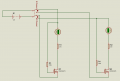
An analog ohm meter internal battery is only 3 or 9V. So I dont think it can be used to test the MOSFET. But you can put your mosfet on a breadboard and test it as using 2 resistors, a mA current meter and a 12V DC supply. the DPDT switch is optional. You can always reverse the polarity of the power supply.

This test is by no mean a complete test. It just give you some idea of what you have in hand. A transistor would give you some reading too but I think it should be different from the MOSFET.

Normal MOSFET has "Gate" on the left, "Drain" in the middle and "Source" on the right when the number is facing upward and the leads are towards you. There may be other pinout configurations but if you show us the readings and how you connect them and we can figure out the rest.
 

Attachments

Last edited:

Thread Starter

AJ Peacock

Joined Aug 11, 2012
34
An analog ohm meter internal battery is only 3 or 9V. So I dont think it can be used to test the MOSFET. But you can put your mosfet on a breadboard and test it as using 2 resistors, a mA current meter and a 12V DC supply. the DPDT switch is optional. You can always reverse the polarity of the power supply.

This test is by no mean a complete test. It just give you some idea of what you have in hand. A transistor would give you some reading too but I think it should be different from the MOSFET.

Normal MOSFET has "Gate" on the left, "Drain" in the middle and "Source" on the right when the number is facing upward and the leads are towards you. There may be other pinout configurations but if you show us the readings and how you connect them and we can figure out the rest.
Thanks, I'll try to do some testing tomorrow.

Don
 

Thread Starter

AJ Peacock

Joined Aug 11, 2012
34
All,

I didn't really have the tools to test the transistor (ammeter), and since it's an H-bridge, I figured I have 2 pair of the MOSFETs on the newly aqcuired board, so I fixed the traces on my board (had 3 fried traces), installed the transistor and installed it in the boat.

Still no left turn! I pulled the board back out and nothing looked fried, so I'm concerned that the original issue might have fried 1/2 of the MOSFET driver,

Can that happen???

I will do a more thorough visual inspection later tonight.

I'm getting very close to just giving up and buying a new auto-pilot, but I really don't want to spend the $$'s

Thanks again guys,
Don
 

Thread Starter

AJ Peacock

Joined Aug 11, 2012
34
Are the motor terminals connected across DQ9 & DQ11 ( SQ10 & SQ12)?
Is there power across L2 & C37?

If so your circuit makes sense.

Can you tell me which transistors are working together in this H-bridge?

What I'm really looking for is which transistor is on at the same time as Q9, since the autopilot is behaving exactly the same now as when Q9 was blown up ( prior to me replacing Q9). I'm thinking that it's teammate might also be broken, but without any visual signs.

Thanks,
Don
 

R!f@@

Joined Apr 2, 2009
10,007
U need to find the left turn driver tht couples to the H bridge gate.

If the rght turn works and the left turn traces were fried then it is possible tht the driver might be fried too
 
Status
Not open for further replies.
Top