Help on a small Project

Thread Starter

RonnieSaha

Joined Aug 8, 2014
7
Hello, this is my first "project" so please keep that in mind when answering my question's!:D

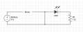
Basically, I want to set up a circuit with an LED and Motor in. The details of which can be found below.

The power supply is simply a 9v Battery which is connected to a switch. This is connected to an LED light with a forward voltage of 2.2v and current of 20mA. Connected to this is a propeller motor with a voltage of 3.7v and current of 100mA. By the way, the circuit is set up in series. My question's are as follows;

1. What resistor will I need to have in the circuit with some explanation?
(I have bought a pack of 1000+ different value resistors at 1/4W)

2. What resistor would I need if I included another LED in the circuit?

Thanks in advance!:)
 

mcgyvr

Joined Oct 15, 2009
5,394
You need to provide a resistor for the LED to limit the current it receives to 20mA..
http://www.ohmslawcalculator.com/led_resistor_calculator.php

and the motor just needs a 3.7V power supply.. It will limit its own current vs the LED which will NOT.

You cannot put it all in series..

You could use an LM317 to create a 3.7V (or close) supply to the motor. (see the datasheet for the LM317 on how to size the required resistors for the desired output voltage.
 

MaxHeadRoom

Joined Jul 18, 2013
28,576
Is this intended to be a practical circuit with those parameters?
Running a motor with a series resistor is not a good idea to start with.
Max.
 

Thread Starter

RonnieSaha

Joined Aug 8, 2014
7
Thanks for the replies.:)

Just to clarify a motor does not require a resistor? (I ask this because without one it got hot)

The aim of this circuit is just for fun because I am very much a novice when it comes to electronics! :D

Would the circuit design that I have attached work if I put the LED in parallel and used a resistor for it. If so, what value would it need to be?
 

Attachments

MaxHeadRoom

Joined Jul 18, 2013
28,576
Rather than put random components together, you need a little 'intelligent design'
First a motor is not a constant load source, you will need to take this into consideration with any component placed in series with it.
Max.
 

sirch2

Joined Jan 21, 2013
1,037
Sounds like you just need to ditch the 9V battery and go for 3*1.2V NiMH rechargeables which would run the motor nicely and then calculate the appropriate resistor for the LED.
 

mcgyvr

Joined Oct 15, 2009
5,394
With 9V running through a 3.7V motor it WILL get hot.. Motors put off some heat anyways but with more than double its rated voltage expect heat and a short life..
Using 3 (or even 2) x 1.5V (AA) batteries would be a better solution.
And you treat them like 2 independent circuits.. (the motor circuit then the LED circuit)..
like this below..
Hows thatfor some advertising... You owe me Subway..
https://dl.dropboxusercontent.com/u/9726802/IMG_20140808_122320.jpg
 

djsfantasi

Joined Apr 11, 2010
9,155
RonnieSaha said:
Would the circuit design that I have attached work if I put the LED in parallel and used a resistor for it. If so, what value would it need to be?
In the attached circuit, the LED and resistor may as well not be there. They are shorted out of the circuit by the wire in the middle.
 

Thread Starter

RonnieSaha

Joined Aug 8, 2014
7
With 9V running through a 3.7V motor it WILL get hot.. Motors put off some heat anyways but with more than double its rated voltage expect heat and a short life..
Using 3 (or even 2) x 1.5V (AA) batteries would be a better solution.
And you treat them like 2 independent circuits.. (the motor circuit then the LED circuit)..
like this below..
Hows thatfor some advertising... You owe me Subway..
https://dl.dropboxusercontent.com/u/9726802/IMG_20140808_122320.jpg
Thanks for the answer, simple but explained everything! :D I think I will use some AA batteries instead. Cheers:)
 

Bernard

Joined Aug 7, 2008
5,784
A little confusing, resistor not needed & with out gets hot?? If you still want to try your parts, first try putting 3 160 Ω in parallel, & put the combination in series with the motor & see how well that it runs. Can add 2 LEDs & 240 Ωs all in series across 9 V, or if you want to go back to origional proposal, put 160 Ωs in series with LED, add another R & LED in parallel, now add 3, 270 Ω all in parallel with LED group. Now add motor in series with the big combo. Draw it out , connect to battery & report findings.
 

Thread Starter

RonnieSaha

Joined Aug 8, 2014
7
I have set the circuit up attached that was suggested. The reason why I used these resistors was that when in this circuit minus the motor branch, the LED worked perfectly. However, when I connected the Motor branch as shown in the diagram, the LED was very, very dim?:S

How can I overcome this issue? :)


EDIT: I realised that I needed a resistor on the motor branch and it all works now:p Thanks
 

Attachments

Last edited:
Top