help with a small project - precise 1rpm motor & circut

Thread Starter

danstar10

Joined Jan 9, 2013
70
Hello!
I am about to embark on a small project to build a star tracking platform for my camera, and I would greatly appreciate a little help regarding the circuit design and component sourcing.
I am new to electronics and have not built anything outside of school projects may years ago, but I like to see myself as a hands on techy person :geek: and I have a soldering iron!

What I am trying to achieve is to build a circuit which would control a motor to turn at precisely 1rpm. This could be done via the circuit controlling the motor directly to 1rpm or by having a precise alternate rpm from the motor and then using small gears to give a resultant 1rpm.

There are various designs online for such circuits, but a lot of them are different and a either way I dont think I would stand a chance without some advice. Here is a design for a similar star tracking platform which will help anyone interested see what my end goal is:
http://www.garyseronik.com/?q=node/52

There is a circuit design at the bottom of the web page:


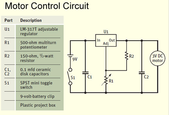
This diagram is by no means strictly what I want to go with, I have no idea if this is the best way to go about it so I would love to hear some ideas and would really appreciate some advice.

Another problem is I have no idea how to source this kind of stuff, so advice on shops or a good website to get components from would help. I am based in London UK.

Thanks in advance!
Dan
 

ErnieM

Joined Apr 24, 2011
8,377
Hey Dan: What that circuit does is give you a way to get an adjustable voltage source, so after many (many) trials your motor will spin at your desired 1 RPM. It's a fairly conventional voltage regulator with some commonly available parts. I'm in the US so I don't know what stores you have there but I could drive a few miles and get all that from a Radio Shack. They also have an EBay store that seems to ship everything for free (unlike their direct online store). ANY distributor worth the name will have all this, if I knew one you would use I could get you part numbers.

It looks like an interesting project. Good luck and welcome to the forums.
 

wayneh

Joined Sep 9, 2010
17,498
Since you essentially need a clock, I'd start with that overall design philosophy.

A voltage-controlled motor - or any "linear" solution - is going to be an awful clock. Well, the percent error might be less than 10%, but that's awful compared to some easy alternatives.

A 555 timer-based clock would be better but I think most folks would start with a crystal oscillator.

[update] I should have read the link first! I guess this approach has been proven to work, at least good enough. I think an easy improvement would be to control motor speed by PWM instead of only voltage. I think, but don't really know, that this would give easier, more linear adjustment and a more stable speed at any setting. It would make small differences in friction drag less influential to the speed.
 
Last edited:

tshuck

Joined Oct 18, 2012
3,534
Since your requirement is a controllable, yet intrinsically unstable parameter(speed), a control system is warranted. A stepper motor, would be my first choice, as the open-loop control is pretty straight forward, avoiding a potentially complex control system, although, a few extra gears isn't too hard;)

Motors characteristics are not uniform across their lifespan and will change with use. For a stepper motor, that is mainly torque, for brushed DC motors, it's everything.
A PID controller could get the job done as it compensates for the error(in this case) in speed and will adjust accordingly.

A brushed DC motor can get this done cheap with relatively simple hardware, but it requires you to make a control system.
A stepper motor can get this done with more complex/costly hardware, yet simpler control scheme...

It all comes down to how accurate this 1RPM needs to be...
 
Last edited:

Thread Starter

danstar10

Joined Jan 9, 2013
70
Thanks for the replies guys.
The accuracy does not need to be super high. basically I will use it to drive the mechanism and take exposures of the night sky of probably a maximum of 30 mins. So if it can keep a reasonable accuracy in that amount of time then it should do the job.

I did not realize there were so many different approaches to this! Sounds like it should be a fun project and I will learn a lot. As I say the design I showed is just an example and my not be the best solution so I am open to any design.

I do not have a big budget, but as long as it is not too expensive (say within £30 or $50 or whatever as a guide, but I am flexible) I am happy to take the approach which will give best results, and is not too complicated to make for a complete novice.

Markd77- thanks for the links, once we get a design settled I will check out rapidonline for the parts - looks promising. I'm not as confident about Maplins as I know the stores but I'll try there too.

So with that bit of extra info, what approach would you guys go for?

Cheers
Dan

p.s. Also would you guys be able to point me to some good online material for novices to read up on the fundamentals? For example if I were to go about recreating the circuit diagram I posted I would not really know how to practically translate it into a working set up.
Cheers!
 
Last edited:

wayneh

Joined Sep 9, 2010
17,498
...what approach would you guys go for?
Put me squarely in the camp of not wanting to reinvent the wheel. The farther you stray from existing designs, the greater risk your solution won't work. Of course that's also how improvements get made!

But I know I've seen similar camera or telescope mechanisms, in this forum even, so I know a lot of folks have worked on projects just like this. You can pick up lots of great of ideas and learn from the painful experiences of others. Be sure to read everything you can find before you start to make choices for your own design.
 

tshuck

Joined Oct 18, 2012
3,534
Put me squarely in the camp of not wanting to reinvent the wheel. The farther you stray from existing designs, the greater risk your solution won't work. Of course that's also how improvements get made!

But I know I've seen similar camera or telescope mechanisms, in this forum even, so I know a lot of folks have worked on projects just like this. You can pick up lots of great of ideas and learn from the painful experiences of others. Be sure to read everything you can find before you start to make choices for your own design.
I would recommend this route also. Being that you are not very well versed in the techniques needed to go the routes I've described, you should find something that works and can be tweaked to what you want.

You won't have much long-term reliability if you don't use a control system, but that may not matter much to you. You could make a system with a H-bridge, 555s, capacitors, and some resistors that will allow you to set a speed for the motor with a simple potentiometer, and keep a relatively constant speed. This would let you set the speed to whatever you'd like.
 

ErnieM

Joined Apr 24, 2011
8,377
The very last thing I would consider doing is use anything that even smells like a pulse on this as I would fear it would shake the camera while the shutter is open, and have each shake rattle and roll recorded for posterity on my picture.

A voltmeter may prove to be a good investment to capture the voltage of a calibrated system.
 

THE_RB

Joined Feb 11, 2008
5,438
The Linistepper open source stepper motor driver kit has been used by a lot of people for telescope driving, it uses a crystal for speed control and will track the telescope or camera with a very high accuracy.

I recently released a C version of the code where you can change one variable to set any desired speed.

I'm not sure if assembling a Linistepper would be within your abilities but basically you just solder the parts into the PCB. Either myself or one of the other people on the Linistepper project could program the PIC for you, if you do not have that capability.

Like I said this is more complex than what you have suggested but will offer a very high level of performance;
http://www.piclist.com/techref/io/stepper/linistep/index.htm
 

Thread Starter

danstar10

Joined Jan 9, 2013
70
From the little bit of reading etc I have been doing it sounds like a stepper motor may be the one.

I like the sound of what you proposed THE_RB, I think I could manage soldering some components to a PCB.

Am I rite in thinking for that approach all I need would be to buy that kit on the website for $35 and get a suitable motor? So the rest is all in the kit? I see there is also a link to a list of good motors for this set up:
http://www.piclist.com/techref/io/stepper/linistep/motors.htm
some of them are pretty pricey, do you think I could get one which is not too expensive for my needs?

I am not sure how complicated programming the PIC would be. Considering I don't know what that means I would probably need to rely on your help! I do know some basic coding but it is pretty limited.

Something that does worry me briefly reading through the assembly instructions is that I will need a large heatsink attached to the circuit which may be pretty obtrusive for my project. Seems on second thoughts this may be a bit overkill for my needs? What do you guys think?
 

THE_RB

Joined Feb 11, 2008
5,438
Hi danstar, changing the code just means you need to change one number, that number sets the speed. There are actually two numbers, which you can use for a second speed (some people use it as a faster "jog" mode).

Generally you will have a lot of mechanical gearing on your telescope, so the motor only needs to be a small, cheap low powered type. That also means you won't need a massive heatsink, just a smallish one.

I don't want to talk you into buying a Linistepper kit if you are not sure it is right for you and that you can easily build it. The best advice would be to suggest you google for "Linistepper telescope" and you should find some examples of people's builds, and problems/successes they have had. Also you can email James at the PIClist website where the Linistepper kits are sold, he can offer some advice re a Lini telescope setup.

Re the ebay links you made, they are for stepper drivers which are not needed if you use a Linistepper, it is the "brains" that sets an exact speed, and also is the stepper driver as well.

As for motors, a lot of old printers, fax machines etc have small stepper motors you can get for free. Otherwise if buying a new motor you can use a cheap size17 (42mm) motor which are available approx $10-18 range.
 

Thread Starter

danstar10

Joined Jan 9, 2013
70
Re the ebay links you made, they are for stepper drivers which are not needed if you use a Linistepper, it is the "brains" that sets an exact speed, and also is the stepper driver as well.
yeah I was thinking may be a stepper motor and driver would be a more suitable / cheaper / easier solution for my needs.

It seems there are quite a few kits out there like this. do you think something in this vein could work for me?
 

THE_RB

Joined Feb 11, 2008
5,438
If you just buy a standard stepper motor driver, you still need an additional circuit to generate the exact frequency or pulses to send to the driver, to make the motor turn.

Or did you already have a circuit to generate an exact frequency of pulses?

With the Linistepper the one kit acts as both the stepper driver AND as a xtal-locked microcontroller than can generate any exact frequency you need, to match your all your telescope gearing.
 

Thread Starter

danstar10

Joined Jan 9, 2013
70
oh ok, I assumed the 'controller' in the 'stepper motor controller' kit meant I could control the freq of the pulses. In that case it is fairly useless for me.

What about this? Or do you think it may not be very accurate:
http://www.ebay.co.uk/itm/190685857371?_trksid=p5197.c0.m619

If this is a no go, it looks like the Linestepper kit may be the best approach. I assume the linestepper does not need to be attached to a computer to operate? And can it run off a remote power supply I could strap to my tracker and use out in a field?
 

Thread Starter

danstar10

Joined Jan 9, 2013
70
I just showed the linestepper solution to someone else and they had this to say:

It looks pretty cool but it doesn't generate the control signals entirely by itself - it needs a "step" signal which would have to be generated by a crystal-controlled oscillator with frequency division. Its focus is on microstepping, i.e. stepping a stepper motor less than one complete step, which you don't really need. Also, it doesn't have full bridge outputs so it can't drive all types of stepper motors.

seems that it is not an all in one solution then?
 

THE_RB

Joined Feb 11, 2008
5,438
oh ok, I assumed the 'controller' in the 'stepper motor controller' kit meant I could control the freq of the pulses. In that case it is fairly useless for me.
...
No, a "stepper motor controller" normally requires step pulses sent to it, which sets the speed.

...
What about this? Or do you think it may not be very accurate:
http://www.ebay.co.uk/itm/190685857371?_trksid=p5197.c0.m619
...
That product will generate a speed by itself but I can't speak for how accurate or adjustable the speed is. Trying to understand the ebay blurbs, it looks to have speed adjustable over 256 settings, I don't know if any will exactly match your telescope gearing (or if you have yet decided on the exact telescope gearing).

... I assume the linestepper does not need to be attached to a computer to operate? And can it run off a remote power supply I could strap to my tracker and use out in a field?
A few people have built telescope drivers with the Linistepper, and using a small 12v battery. You should have a google for their results.

...I just showed the linestepper solution to someone else and they had this to say:

It looks pretty cool but it doesn't generate the control signals entirely by itself - it needs a "step" signal which would have to be generated by a crystal-controlled oscillator with frequency division. Its focus is on microstepping, i.e. stepping a stepper motor less than one complete step, which you don't really need. Also, it doesn't have full bridge outputs so it can't drive all types of stepper motors.
Normally your friend would be right, but the Linistepper is not just a driver, it contains a PIC micro so it can do whatever you program it to do. As I stated earlier in the thread I have released a couple of versions of high accuracy telescope drivers, you just need to set one number to set the exact speed and program the code into the PIC.

Re the types of motor, the Lini will drive all 5,6 and 8 wire motors of a suitable size, it won't drive 4 wire motors. Re the microstepping, the Lini is the smoothest driver on the market as it has both microsteps AND special linear current smoothing. THat is one resone it is liked by telescope people, it does not "buzz" and shake the telescope as the motor runs, like the majority of stepper drivers do.

Anyway as the guy who designed the Linistepper I don't want to look like I am trying to talk you into buying a kit. That is just one way of driving a telescope. Google will find some Lini users, but one telescope build I remember recently is this one (please have a read, it might give you ideas);
http://www.cnczone.com/forums/stepper_motors_drives/137484-drive_1_8_degree_stepper_1_rpm.html

He started off thinking of building a 555 timer controlled telescope driver, and ended up with a very nicely made, high accuracy Linistepper driven setup. It's a long thread but worth the read, as it discusses the gearing systems and speed math etc.
 
Top