 Facebook
 Google
 GitHub
 Linkedin
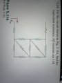
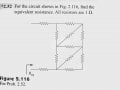
Hello!!!'m a first-year electrical engineering student, and today I came across this question. I wanted to use the wye to delta transformation to solve it, but I'm having a hard time visualizing the simplified circuit. How should I know which resistors to choose for the transformation, and where should I place the transformed resistors?Any guidance would be greatly appreciated.

Attachments
-
 3.3 MB Views: 57

")


