Help needed with a simple radio circuit

Thread Starter

AlwaysNumber1

Joined Dec 4, 2016
52
Hello everyone !)

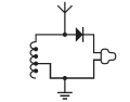
Have just constructed the circuit, shown below, and have the following questions about it:

1. How does the resonance occur (as usually it occurs in LC circuit) ?
2. How does demodulation happen ? (how is signal changed to sound)
3. Why do we need to use ONLY high impedance headphones ?

Will be glad to hear your answers !)
 

Attachments

AlbertHall

Joined Jun 4, 2014
12,338
1. All inductors have parasitic capacitance (between the turns) and so have a self-resonant frequency.
2. The diode is the simplest way to demodulate amplitude modulated signals.
3. First, low impedance 'phones will load the coil and and so reduce its Q factor which will reduce the signal level which will be very low anyway.
 

Thread Starter

AlwaysNumber1

Joined Dec 4, 2016
52
1. All inductors have parasitic capacitance (between the turns) and so have a self-resonant frequency.
2. The diode is the simplest way to demodulate amplitude modulated signals.
3. First, low impedance 'phones will load the coil and and so reduce its Q factor which will reduce the signal level which will be very low anyway.
Thanks once again for replying for my questions !)

Generally got it, but could u please clarify each point and write a little bit more ?
 

AlbertHall

Joined Jun 4, 2014
12,338
1. http://www.analogictips.com/when-inductors-self-resonate/
2. http://www.radio-electronics.com/in...n/am-reception/diode-detector-demodulator.php
3. Think of the tuned circuit as a pendulum. If there is very low friction then the pendulum will swing for a long time. If the friction is increased this takes energy from the pendulum and its swing will slow more quickly. The same sort of thing happens with a tuned circuit. In the case in point, low impedance 'phones across the tuned circuit take more energy and reduce the effectiveness of the tuning. Hence the need to use high impedance 'phones.
 

AnalogKid

Joined Aug 1, 2013
10,971
While you are surrounded by radio waves from dozens or hundreds of sources, the energy level of each signal is in the microwatt range. So when this circuit tunes in a station, only microwatts are available to drive the headphones because there is no RF or audio amplifier. As noted above, this energy is coming from a high impedance source (the antenna) so any significant loading will "short out" the signal. High impedance headphones, such as old crystal headphones, do not load the circuit significantly, and produces the loudest audio.

ak
 

Thread Starter

AlwaysNumber1

Joined Dec 4, 2016
52
1. http://www.analogictips.com/when-inductors-self-resonate/
2. http://www.radio-electronics.com/in...n/am-reception/diode-detector-demodulator.php
3. Think of the tuned circuit as a pendulum. If there is very low friction then the pendulum will swing for a long time. If the friction is increased this takes energy from the pendulum and its swing will slow more quickly. The same sort of thing happens with a tuned circuit. In the case in point, low impedance 'phones across the tuned circuit take more energy and reduce the effectiveness of the tuning. Hence the need to use high impedance 'phones.
Just to make sure that I got it the right way:
1. When I change the number of coils in an inductor, the frequency that I hear is the self-resonant frequency of an inductor with the number of coils that I select ?
2. So, the headphones also play a role of the filter that passes only low frequencies and thus smooth out the signal to hear the sound ?
 

AlbertHall

Joined Jun 4, 2014
12,338
A parallel tuned circuit at resonance, from the outside, is a high impedance, but it is at this point that the maximum current is flowing round the loop between the capacitor and inductor. In this video you can see the current continues to flow round the LC circuit even though nothing else is connected to drive it.
 

Thread Starter

AlwaysNumber1

Joined Dec 4, 2016
52
A parallel tuned circuit at resonance, from the outside, is a high impedance, but it is at this point that the maximum current is flowing round the loop between the capacitor and inductor. In this video you can see the current continues to flow round the LC circuit even though nothing else is connected to drive it.
Actually I have an easier explanation
This video girls just for a perfect LC circuit, but in our case there is also resistance, so at self resonant frequency of not ideal inductor current flow at maximum rate
 

AlbertHall

Joined Jun 4, 2014
12,338
If there is resistance (and as you say there will be) then that oscillation will die away. The greater the resistive losses are, the quicker they will die away. That is why the high impedance 'phones are important.
 

Thread Starter

AlwaysNumber1

Joined Dec 4, 2016
52
If there is resistance (and as you say there will be) then that oscillation will die away. The greater the resistive losses are, the quicker they will die away. That is why the high impedance 'phones are important.
No, I mean the following:
We should think about parallel LC circuit as RLC parallel circuit
Is it correct ?
 
Top