Facebook
 Google
 GitHub
 Linkedin

Your suggestion in post #8 was good.
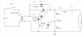
That is a, "pulse only" circuit where the transformer provides some voltage higher than 13.8V peak.
Current initially goes through R2 and D4 as the transformer voltage ramps up above the voltage already in the batteries. When the voltage across R2 is enough to fire the SCR through R1, the SCR fires.
R5 is a limiter with dubious purpose. It causes the limiting circuit to consider both the battery voltage and the charging current. F1 is seriously wrong for a 20 amp charger.
So, as the voltage at the top of R3 increases, R7 directs some of it to the base of Q2. When the voltage at the base of Q2 is more than about .6 volts, Q2 shorts out R1 and stops the drive to the SCR.
This is absurd because you can not turn an SCR off until the transformer current drops to zero. If this were a DC power supply, you could NEVER turn the SCR off and the battery would melt.
So, how to fix the absurd? Give Q2 a time delay.
This can be done at the collector or the base.
The collector is already involved in a time sensitive way, so that would need a balancing act to get it right. The base is therefore our suspect.
Add a capacitor between the base and the ground of Q2. It will charge to an average voltage related to the battery voltage plus the voltage across R5. As the battery voltage rises and the charging current decreases, the capacitor voltage will more and more resemble a proportion of the voltage on the battery instead of the current pulses. You want the capacitor to hold the base of Q2 high enough to defeat the firing current in R1 when the next pulse arrives. That's your minimum time limit.
Now add a resistor between the base of Q2 and the voltage on the capacitor to keep the capacitor discharge slowed down. About 75 ohms should work. What capacitor won't lose 1/10th of a volt in 17 milliseconds when being loaded with 750 ohms?
That is a, "pulse only" circuit where the transformer provides some voltage higher than 13.8V peak.
Current initially goes through R2 and D4 as the transformer voltage ramps up above the voltage already in the batteries. When the voltage across R2 is enough to fire the SCR through R1, the SCR fires.
R5 is a limiter with dubious purpose. It causes the limiting circuit to consider both the battery voltage and the charging current. F1 is seriously wrong for a 20 amp charger.
So, as the voltage at the top of R3 increases, R7 directs some of it to the base of Q2. When the voltage at the base of Q2 is more than about .6 volts, Q2 shorts out R1 and stops the drive to the SCR.
This is absurd because you can not turn an SCR off until the transformer current drops to zero. If this were a DC power supply, you could NEVER turn the SCR off and the battery would melt.
So, how to fix the absurd? Give Q2 a time delay.
This can be done at the collector or the base.
The collector is already involved in a time sensitive way, so that would need a balancing act to get it right. The base is therefore our suspect.
Add a capacitor between the base and the ground of Q2. It will charge to an average voltage related to the battery voltage plus the voltage across R5. As the battery voltage rises and the charging current decreases, the capacitor voltage will more and more resemble a proportion of the voltage on the battery instead of the current pulses. You want the capacitor to hold the base of Q2 high enough to defeat the firing current in R1 when the next pulse arrives. That's your minimum time limit.
Now add a resistor between the base of Q2 and the voltage on the capacitor to keep the capacitor discharge slowed down. About 75 ohms should work. What capacitor won't lose 1/10th of a volt in 17 milliseconds when being loaded with 750 ohms?
Attachments
-
 22.9 KB Views: 35