 Facebook
 Google
 GitHub
 Linkedin
Hi Everyone
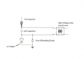
I have a high voltage pulse circuit that has a free wheeling diode to protect the SCR
The only problem I have is the diode is wasting energy and lowering the output voltage from the transformer
Would the 1UF capacitor on its own be enough to protect the SCR and remove the diode or should I use a diode and zener snubber ?
The SCR is a BT151-800R
Any advice appreciated
Attachments
-
 20.5 KB Views: 35


