Facebook
 Google
 GitHub
 Linkedin
Hi everyone,
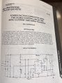
I'm currently working on a PFC boost converter and had a few doubts regarding the duty ratio, especially in relation to steady-state and transient response.
I'm referring to Ned Mohan's First Course on Power Electronics, where the author mentions that applying a duty ratio of
D(t) = 1 − Vs·|sin(ωt)| / Vd
can yield the required output voltage. My question is: how does this duty ratio result in a sinusoidal input current?
Specifically, I’m wondering—if I design the circuit without any feedback control and simply apply this duty ratio to the switch, will I actually get a sinusoidal input current? If not, why? In rudimentary power converters, we had a fixed duty ratio that we gave to the switch to get the required output..here we have two conditions to satisfy: sinusoidal input current and fixed output voltage..how does one duty ratio satisfy both? I referred to some YT lectures and textbooks regarding this doubt but wasnt able to find an answer to it (maybe my doubt itself is vague and I lack the knowledge to grasp the answer that is implicitly stated :*) . ).
I understand that the duty ratio is shaped to mimic the input voltage waveform, but I’m unclear on how that alone ensures the input current follows a sinusoid. Does the input current waveform depend on the inductor dynamics or the presence of a current loop?
Would really appreciate any insights or clarifications from the community.
Thanks in advance!