Help needed fixing Pc’s 1000w psu

Thread Starter

Bigfillly

Joined Jan 4, 2019
73
hi,
I have a 1000w psu for my pc/mining rig, I’m looking at running it off solar and x6 12v lorry batteries, I am trying to use the psu but connecting 12v/5v/3v to the circuit board at the correct place with dc-dc step down modules,
I started testing for voltage on the circuit board, I got to 2 points and the house electrics tripped out, I flicked the houses breaker back on and went to turn the psu on again but the house tripped off again, for some reason the psu is shorting but can find out where,
This is the name of the psu
1B566B22-00C5-45B8-831A-91428B592D0E.jpeg
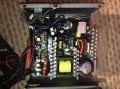
This is a top view of it
4C31C51B-B0FC-4B0E-A242-DD9E2F64C387.jpeg
And this is where I think I tested for volts which is in the bottom right near the big capacitor
501098A7-318F-4553-AE6A-D9EACF5C9675.jpeg
Any help would be great,
Thanks very much,
Phil.
 

Attachments

Last edited:

Dodgydave

Joined Jun 22, 2012
11,302
Is it tripping the Earth leakage device or the just the mains breaker ( ie over current)?

What's the component that's been shorted out with your test probes?
 

Thread Starter

Bigfillly

Joined Jan 4, 2019
73
I have to say I’m far from an expert,
I’m not sure why it’s tripping out, I can tell you it is tripping out when i flick the switch at the back of the psu, not when the psu is actually running, so it has to be tripping really early on the board?
Thanks,
Phil.
 

Thread Starter

Bigfillly

Joined Jan 4, 2019
73
Ok, I’ve tracked back from where the burn marks are and it goes to this
Big_part_cropped.jpeg
I believe it’s a thermistor, there isn’t any rating on either side, I’ve checked for ohms and it’s showing nothing, I’ve also checked continuity and it has continuity,
Could this be the reason for tripping out when the switch on the back of the psu is turned on (not even having the psu running)
Thanks,
Phil.

Moderators note : cropped essential part of image.
 

Attachments

Last edited by a moderator:

Thread Starter

Bigfillly

Joined Jan 4, 2019
73
There is also a zener diode next to it, could that be what it causing it to trip out?
Here’s the zener, bottom right next to the thermistor, nest to the capacitor
E9009FE0-207B-41DF-8E83-6F596D8FC7A4.jpeg
 

Thread Starter

Bigfillly

Joined Jan 4, 2019
73
I’ll put it back together minus the thermistor and let you know,
I’ve checked the zener with a psu set to 0.10 amps, as I don’t have the diode test on my dvm, the zener doesn’t test right either?
I’ll try without the thermistor now
 
Last edited:

Thread Starter

Bigfillly

Joined Jan 4, 2019
73
Ok, I’ve put it back together without the thermistor, it did the same and tripped out but I did notice a sparked at the switch wires (see pic)
A47D845A-16EC-49A8-9FAB-99B6C7CA4142.jpeg
So I’ve just checked for continuity between the switch and earth, there is a reading of 456 between earth and neutral?
Is it want you said earlier, the earth leakage device? Where is that and how do I check it?
Thanks very much,
Phil.
 

Alec_t

Joined Sep 17, 2013
14,313
There should be very little resistance between mains earth and neutral if the psu is plugged into the mains supply.
 

Thread Starter

Bigfillly

Joined Jan 4, 2019
73
Thanks very much for the replies,
So this would cause a spark at the switch?
Where do I look and check next, would the zener diode cause this problem?
Thanks again,
Phil.
 

Dodgydave

Joined Jun 22, 2012
11,302
Not zener diode, unplug from the mains, and test on ohms between Neutral and Earth and, Live and Earth, for low resistance, if you're getting under 7.5K ohms it's likely to be suppresion capacitors faulty.

Here is a typical smps circuit, the mains input is on the top left..


1.bmp.jpg
 

Thread Starter

Bigfillly

Joined Jan 4, 2019
73
Thanks very much again dodgydave,
I’ve checked where you said to and there’s nothing at all between them, I had the ohm set to 20k and checked as in the pic
8E7C22E2-5C09-4456-A27B-ED8B89325C1A.jpeg


A1A4C263-E23D-4BAB-920C-BC43D26DC7DA.jpeg
is this the suppression capacitor and how can I test it?

Also, as I was planning on trying to connect a dc supply after the 240v reducer, where would be best to connect it to? It could be that I don’t need to fix the 240v end,
Thanks again,
Phil.
 

Attachments

Last edited:

SLK001

Joined Nov 29, 2011
1,549
There has to be a fuse just off the mains on the PCB. If there was anything shorting on the PCB, that fuse would be the first to go (not your house circuit). The problem has to be in the wiring prior to the fuse.
 

Dodgydave

Joined Jun 22, 2012
11,302
Ok, just to refresh, what resistance are you getting across Live and Neutral on your psu input?, and it sounds like there is no Earth leakage if you're getting over 20K resistance.

The item in the yellow box looks like an Inductor filter with green suppresion caps.

The problem may be on the Secondary side, it could be the Mosfet blown taking too much primary current.
 

Thread Starter

Bigfillly

Joined Jan 4, 2019
73
I’ve just checked and I’m getting no reading at all across neutral and live but the thermistor is still out, shall I put it back in and test again?
Dodgydave how did i break it whilst I was checking for volts at certain areas, I didn’t think I could blow anything doing that?
Thanks very much again,
Phil.
 

Thread Starter

Bigfillly

Joined Jan 4, 2019
73
I’m in the uk, and yes it’s tripping at the mains breaker,
How does it happen that is blows something using a multi meter checking for volts?
I’ll put it back in and retest,
Thanks very much,
Phil.
 

atferrari

Joined Jan 6, 2004
4,769
Sorry but I cannot make sense of what the OP is actually trying to connect to what.
If trying to go away by using batteries and DC-DC step down modules, where in the diagram provided by dave, would they be connected?
 
Top