Help needed designing a resistance sensitive circuit

Thread Starter

Marcus4477

Joined Dec 19, 2020
4
Hi All! I’m hoping an expert can steer me in the right direction.

I’m developing a set of custom paddle shifters on my car steering wheel. How it works is there are two wires taken from a stock shift button on the floor shifter that I extended through the steering column to a set of paddles i installed on the steering wheel. Each wire goes to a paddle, one for upshifting one for downshifting. When a paddle is pressed the current to that paddle is grounded and the transmissions shifts. Fairly simple.

The problem is there is only 1 available wire in the steering column's clockspring. Previously I disconnected the cruise control and used that wire but I would like to gain functionality of both the paddles and the cruise control.

I understand that the stock buttons on the steering wheel each have a different electrical resistance which allows many switches to operate through the fewer number of wires of the clockspring. I believe this works on the principle that the electronics can tell from the resistance which button is being pressed on the wheel. (Please correct me if this is wrong). Using the same principal I would like to add some type of resistance sensitive circuit on both sides of the single open clockspring wire so that I could operate both paddles through the single wire. Any suggestions? Please be as detailed as possible as I don't know much about electrical engineering. Thanks you! - Marc
 

Ian0

Joined Aug 7, 2020
9,803
I understand that the stock buttons on the steering wheel each have a different electrical resistance which allows many switches to operate through the fewer number of wires of the clockspring. I believe this works on the principle that the electronics can tell from the resistance which button is being pressed on the wheel.
Yes - that is correct for a lot of multi-switch keypads, but there is one crucial difference with the paddles - you can operate them both at once!
So, does operating both paddles at the same time have any function (selecting neutral, or reverse for instance)?
 

Thread Starter

Marcus4477

Joined Dec 19, 2020
4
Hi! Thanks for responding!

No operating both paddles at once has no function. If both paddles are pressed simultaneously only the first to complete the circuit would function and the second would not function unless it is held pressed then it would function only when the first paddle is released. It's a good question but it's not something I'm concerned with as they would only be operated one at a time. So what do you think?
 
Last edited:

Ian0

Joined Aug 7, 2020
9,803
Presumably, you've no access to a +12V supply either. . . .

There is a pullup resistor , say 10k at the receiver.
Then one switch connects to directly to ground and the other via 10k.
So with no switch pressed the output is 12V, with switch 1 pressed, the output is 0V and with switch 2 pressed the output is 6V.
A couple of comparators then sorts out which switch has been pressed.
Switch 1 always overrides switch 2.

With two resistors, it is possible to detect the "both switches pressed" scenario.
Say R1=5k and R2=10k.
Switch 1 gives an output of 4V and switch 2 gives 6V, and both together gives 3V.
 
Last edited:

Thread Starter

Marcus4477

Joined Dec 19, 2020
4
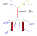
Ok so I made a diagram to help me understand what you are saying. The numbers indicate places where the resistors/comparators may go.

Where would the resistors go and where would the comparators go? Also, if the resistors are 4V or 6V that will work with the rest of the 12V car/receiver right? Thanks!

Untitledggfdgdf.png
 

MisterBill2

Joined Jan 23, 2018
18,463
OK, what you need is one IC, a quad compparator set up as two window comparators so that each paddle switch will trigger a window comparison, , while both at once deliver a different voltage that does not trigger either functions. Aside from noise filter capacitor each part needs 3 resistors. Fairly simple indeed.
 

crutschow

Joined Mar 14, 2008
34,409
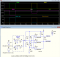
Here's the LTspice simulation of a comparator circuit that should do what you want.
It basically uses one 2-comparator window comparator for the lower paddle voltage (Down) and a third comparator for the higher paddle voltage.

V1, V2 and the two switches simulate operation of the paddles.

The "In" signal goes through the single clock-spring wire to the external comparator circuit.

1608448401317.png
 

MisterBill2

Joined Jan 23, 2018
18,463
OK! Post #7 shows the concept that I had simplified a bit by using one comparator twice. Good thinking Crutschow! Of course the LM339 is a 4 comparator package so not much cost saving, but the cool factor is better. I don't see much room for improvement, unless the output current is not high enough. R7 and R8 can be cheaper 4K7 10% resistors instead of the 1% kind shown and it will work just the same.
 

Thread Starter

Marcus4477

Joined Dec 19, 2020
4
Hi All! Thanks so much for your replies Crutschow, MasterBill2 and Ian0.

Ian0 - I could make 12V power available but only on the steering column side of the clockspring. I don’t know if this would affect the design or make it easier?

Ron - I had gone with a wireless Bluetooth unit in the past but there was a slight delay that was very noticeable and the direct wire had a much less delay so it felt much better. Funny, but with paddle shifters for transmissions (and throttle response) any delay is very noticeable and undesirable, with the best setups limiting delay to just 700 milliseconds and mostly all of that is internal to the transmission. Ideally it should feel like a light switch in a house - as close to instant as possible.

Which brings to mind – Crutschow's diagram (thank you so much!) shouldn’t create any delay in the signal due to all the resistors and comparator(s) as compared to a simple direct wire, right? Apologies if I should have mentioned the need to avoid any delays earlier I didn’t think it could be an issue with direct wire.

Crutschow - It appears from your graph that the voltage/amperage/watts of the current to the receiver should be about the same going into the paddles from the stock shifter, right? This is important because too weak may not signal the receiver and an amplified current may burn something out. With these new cars some wires have 12V current others from the computer only 5V or sometimes much less – would this affect this design?

I don’t have any experience reading electrical diagrams so please afford me some patience – I’m trying to assemble a parts list:

  • Do I need 1 or 3 of Comparators (for U1, U2, and U3) type LM339/393
  • 1 of R1= 10,000 Ohm resistance
  • 1 of R2= 5,000 Ohm resistance
  • 1 of R3= 15,000 Ohm resistance
  • 1 of R4= 500 Ohm resistance
  • 1 of R5= 2,000 Ohm resistance
  • 1 of R6= 1,000 Ohm resistance
  • 1 of R7= 4,990 Ohm resistance
  • 1 of R8= 4,990 Ohm resistance

Is this correct? Any suggestions of an online seller to get these parts?
Alternatively, any suggestions where I could get this built?

Thanks again for all your help.
 

MisterBill2

Joined Jan 23, 2018
18,463
Please understand that the comparators shown by Crutschow are all part of a single 14 pin IC. It is also probable that those outputs may need a bit of amplification to drive your shifting circuit, which we know nothing about.
And you are certainly correct about delays, even the comparator circuit will have a delay of several microseconds. Delays are one of the other reasons why car electrical systems to not all use a single serial data bus to communicate with all the parts of a car. That I dea was foolish when first suggested but now it would be really dumb.
 

crutschow

Joined Mar 14, 2008
34,409
Crutschow's diagram (thank you so much!) shouldn’t create any delay in the signal due to all the resistors and comparator(s) as compared to a simple direct wire, right?
There will only be microseconds of delay, which is totally negligible in this application.
With these new cars some wires have 12V current others from the computer only 5V or sometimes much less – would this affect this design?
No.
The circuit will work equally well on 5V or 12V.
Is this correct? Any suggestions of an online seller to get these parts?
Alternatively, any suggestions where I could get this built?
That's the correct parts, but you should add a coupling decoupling capacitors from the power to ground (which I didn't show), one near the switches and one at the LM339. An electrolytic type of 4.7 to 10μF should be fine.

The supplier to use depends upon where you live.
In the USA, Mouser, Jameco, or Digi-Key are all good.
 

Ian0

Joined Aug 7, 2020
9,803
The reason I asked about +12V is that it would simplilfy things.
One switch could go to 12V, the other to 0V and when neither was pressed it could float at 6V.
But without 12V on the steering wheel it's a non-starter. @crutschow 's circuit is the way to go.

I have a car with paddle-shift gearchange, and can understand why delays are out of the question, and a reliable operation is essential!
 

MisterBill2

Joined Jan 23, 2018
18,463
If +12 volts is not available at the steering wheel then tha circuit can still be used, but the resistors will need to be re-arranged a bit.
So the question is what source voltage is available on the steering wheel? Going back I only see ground, (common) as the available voltage. So the input part of the circuit will need to be re-arranged a bit to have the switches connecting to ground. That can work just as well, but with a slight re-arrangement of resistors.
 
Last edited:

crutschow

Joined Mar 14, 2008
34,409
Good point about the supply voltage possibly not being available by the switches.
Below is the circuit modified with the switches going to ground.
The "In" connection point is the clock spring wire between the switches and the circuit outside the wheel.
As noted, you can use the LM339 which has four comparators in one package.

1608573996926.png
 
Last edited:

MisterBill2

Joined Jan 23, 2018
18,463
The problem discovered was that there was no source of _12 volts on the wheel. So the circuit was rearranged to use the available common side of the 12 volts, which is present on the wheel. The Corvette circuit is good, but it was designed as OEM, not as an add-on function. Doing it from the very start makes it a lot simpler.
 
Top