 Facebook
 Google
 GitHub
 Linkedin
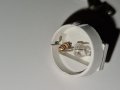
I opened it up again and this time the coloured cover popped off to reveal a resistor after all!Do you still have it open? Can you take photos? Just to be sure.
Attachments
-
 3.1 MB Views: 13
 -
 1.6 MB Views: 15
")
 Thanks so far for the discussion guys.


