Hi all
Measured the signal at Input 1 and Input 2, results as follows for Peak to Peak:-
Input 1 = 120mv Peak - Peak
Input 2 = 95mv Peak - peak
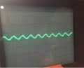
Also attach my scope traces although its very bright and they didn't come out that well.
Just seen the 5th post above, so I need the "Control Voltage" and "Supply Voltage" to be exactly the same voltage say 9 Volts and it should work, ok I will try that and report back as well.
The signal looks like DC, but is supposed to be AC sine wave(s).
So disconnect CD4066, Pin1, from the 47k resistor, then measure at the 47k resistor.
(The 0.01u cap at MC1358, pin12, should be blocking DC from pin12)
Hi
Discoinnected CD4066 Pin 1 from the 47K resistor, no difference however what I did find was that I do have a sign wave 0.4V Peak to Peak right at the detector right at the start of the circuit, but once it enters the MC1358 through the 22pf cap it appears to be lost, I think I need to go back all over the circuit and check for a break or mis-soldered component etc and double check everything to be sure.
I also tried changing the voltage form 5V to 9V but no difference, however with what I found above I am not confident now it is right in the first place.
Also thanks to everyone for all your patience, this IC / area is new to me so although I understand some of the terms i don't know them all so please excuse all my questions, its just me trying to gain a better understanding of whats going on.
Heres the sine wave at the beginning, this sounds like it is more like what should be expected.
What are you making?
The very old obsolete MC1358 was used to amplify the 4.5MHz IF and detect its FM in an old TV. An AM radio does not use FM and does not work at 4.5MHz. The 22pF capacitor passes the 4.5MHz in a TV, not audio.
The CD4066 must have the audio signal DC biased within its power supply voltage range.
Hi Audioguru
I am adding FM to an AM radio so the circuit is to do this. This is the IC that it is suggested to use so it must have worked in the past, from the help so far I am currently revisiting my circuit layout as have a sine wave going in from the detector diode but thats about it so need to recheck my circuit first.
An AM radio receives 1MHz and has a 455kHz IF.
An FM radio receives 100MHz and has a 10.7MHz IF.
Your antique TV IC receives 4.5MHz and might not work at 10.7MHz.
They are all completely different.
The signal feeding the AM detector diode has nothing to do with an FM radio. The FM radio must have its own 100MHz RF amplifier, its own !00MHz minus 10.7Mhz oscillator, its own mixer, its own 10.7MHz IF and its own FM detector circuit that works at 10.7MHz.
An extremely cheap and simple FM radio is sold at Dollar Cheapy Stores. It works but very poorly.
Hi
Thank you for your comments, I will try and answer some of them.
T1 and T2 shown in the circuit are actually 10.7 mhz, the board i am adding is an fm detector using my ‘antique’IC (good description) . I cant visit the dollar store as not my currency and a bit far / wet for me to commute!
Sorted!!!
I found that at pins 9&10 of the MC 1358 that i had not soldered my wires to make contact with the IC pins, in addition my ground for pin 6 was also missing. Looking at the circuit again i disconnected all of the Cd4066 and replaced it with a 2 way flick switch and with a bitbof rewiring - bingo i have FM and AM at the flick of a switch.
Thank you crutschow and eetech00 for your constructive and very helpful comments, it has been a pleasure being my first post dealing with you both and you encouraged me to the point of sorting it out which is great.
Have a good one.
This is a Very interesting thread, in that the discussion wandered off to the FM system IC. Usually those would also work at 10.7 Mhz, with components adjusted for the higher frequency.
But where was the 10.7Mhz signal coming from in an AM radio??? OR is is a shortwave radio??
Just because normal broadcast is AM does not mean that there is no option of others using FM in the same band.
IN FACT, would anybody even notice some narrow FM deviation on an AM broadcast station? I recall that back during the Cuban Missile Crisis some clear channel broadcast stations were sending teletype code using 170 Hz carrier frequency shifting, and nobody ever noticed.
Hi Misterbill2
You are indeed correct and interesting about the cuban crisis, i was originally struggling to get the cd4066 to switch as you say the thread went a bit “off frequency” to use a pun about the 10.7mhz which was never actually the issue. It was just a question about a switching issue at the IC and the radio is an AM CB radio i am adding FM into so the 10.7 mhz is already there. A couple of members were helpful with the sinewave info and that got me checking the circuit finding some errors and replacing the IC with a switch and away i went. Have a good one and thanks for the follow up.
The ony place that I have seen FM on CB radios is in the UK, and there the channels are offset from the US CB channels. So unless you find somebody with a "Galaxy" CB radio you may not hear much.
It does seem like an interesting experiment. What part of the world are you in? This site has folks from al over the world is why I ask.
 Facebook
 Google
 GitHub
 Linkedin