 Facebook
 Google
 GitHub
 Linkedin
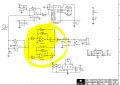
This is schematic of TDS (Total Dissolved Solids ) sensor module. Can someone help me in understanding the purpose of highlighted part of this circuit.
for more details about this sensor , visit https://www.dfrobot.com/wiki/index.php/Gravity:_Analog_TDS_Sensor_/_Meter_For_Arduino_SKU:_SEN0244
for more details about this sensor , visit https://www.dfrobot.com/wiki/index.php/Gravity:_Analog_TDS_Sensor_/_Meter_For_Arduino_SKU:_SEN0244
Attachments
-
 62.8 KB Views: 70


