help me understand grounding..?!

Thread Starter

buffon2009

Joined Dec 7, 2011
28
hello everbody

i wanna physical understand of why we choose (in the case of batteries) the negative terminal as a path for discharge any noise

when there's a wire and an electric field arround it that electric field is varient as it's for example for a radio channel

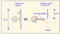
i draw that picture for facilite my question

why in one case it blocks current and in the other it flows the current

as i want to block current not make current flow
 

wayneh

Joined Sep 9, 2010
17,498
I can't understand your question when you talk about electric fields and blocking current. You can block current by cutting the wire.

Bringing noise signals to "ground" (battery negative) ensures that they don't get amplified in other circuitry. Any voltage above ground might be mistaken for signal.

That's just a wild stab at guessing about what you are asking.
 

Thread Starter

buffon2009

Joined Dec 7, 2011
28
I can't understand your question when you talk about electric fields and blocking current. You can block current by cutting the wire.

Bringing noise signals to "ground" (battery negative) ensures that they don't get amplified in other circuitry. Any voltage above ground might be mistaken for signal.

That's just a wild stab at guessing about what you are asking.
let's begin step by step

the actual directon of current in a circuit of battery is from negative side to positive side .. is that ok?
 

wayneh

Joined Sep 9, 2010
17,498
The arbitrary convention is the opposite of that; current flows positive to negative in most discussions. (Not all, but that's the default.) It has nothing to do with the reality of electron movement.
 

vk6zgo

Joined Jul 21, 2012
677
There is nothing magical about the negative terminal--we can ground the positive terminal,or neither.
Your drawing shows magnetic fields not electric ones.

You really need to go back to the basics & learn from a book------we can't supply 6 months worth of an Elementary Electrical Theory course in a few paragraphs.
 

Thread Starter

buffon2009

Joined Dec 7, 2011
28
There is nothing magical about the negative terminal--we can ground the positive terminal,or neither.
Your drawing shows magnetic fields not electric ones.

You really need to go back to the basics & learn from a book------we can't supply 6 months worth of an Elementary Electrical Theory course in a few paragraphs.

i asked this question because i tried to use a coaxial cable as antenna when i connect the shield to the negative terminal of battery the received signal is more perfect than make shield unconnected

the shield is a conductor and there's an varying electrical fields and when leave it unconnected the received signal is bad , when connect it to the negative terminal of battery of the device the received signal is perfect why ?!!!! !

i got confused please help me understand that
 

vk6zgo

Joined Jul 21, 2012
677
The effect of an antenna feeder which has one side disconnected has nothing to do with connection to the battery negative terminal.
Back in the day,many TV & FM radio antenna feed cables were balanced,& were connected at the receiver end via RF transformers ( neither side connected to ground).
If you disconnected one side of the cable you got poor reception,just as you do with the shield side of a coaxial cable disconnected.

You have this idea that there is something magical about the negative terminal of a battery.
There is not-----in the early days of Semiconductors PNP transistors were common,which required a negative Collector supply.
In radios using such circuitry,the positive battery terminal was connected to ground.

Many Operational Amplifiers require both a positive & a negative supply.
The positive supply has its negative terminal connected to ground,whereas the negative supply has its positive terminal connected to ground.
This common ground still looks like "ground" to signal & noise.
 

MrCarlos

Joined Jan 2, 2010
400
Hello buffon2009
Without delving much with regard to the flow of electronic current we can say that:
Since the electronic current refers to the flow of electrons, and they have negative charges. then the electronic current is a flow of electrons from the negative terminal to the positive terminal where there are not electrons.
But there are holes !
Then: if electrons go from here to there, the holes come from there to here.
If an electron moves beyond, leaving an empty space (hole).
That's all about it.

Negative & ground.
We need 2 conductors with different polarity so that there is a flow of electronic current. And so things happen: Turning on a radio, a lamp, LED, Etc.
The same applies to the antenna.
But in this case the electronic current flows in both directions. At a rate which depends on the transmission frequency.

Take a look at the attached image.
What if the ground terminal is not connected to the antenna ??
It will not be the maximum energy transfer between the transmitting and receiving antennas.
The shield of the coaxial cable is to shield it and reduce noise induction.
And, of course, to close the circuit and the electronic current to flow.
In short, there is much to talk about this issue
 

Attachments

Thread Starter

buffon2009

Joined Dec 7, 2011
28
thanks MrCarlos for the clear reply

ok i already now understand that there's holes and they move also as electrons

in the Case of Antenna i already Know that the current pass two ways depending on the transmission frequency

But if i connect the Sheild to the ground the Current will Pass to ground and that will reproduce induction. or electric field that will effect the inner of the Coaxial Cable

You talk about maximum energy i don't understand what ground relate to maximum energy

could you please answer me with details
 

MrCarlos

Joined Jan 2, 2010
400
Hello buffon2009

Talking about: -maximum energy-

It is a little hard to explain in a few words or a few paragraphs that theory: Maximum Power Transfer.
But let me try.

Have a source of energy. (The transmitter).
We have a device against what we want to transfer that energy. (The receiver).
We also know that two (1)conductors (of different polarity) are required for the electronic current flows.
Connected to the same energy supplier.

In the case of the antenna there are mixed -principally- two theories: that of electromagnetism and electronics.

Based on this we can say that the Maximum Energy Transfer occurs when both, the transmitter and receiver, have the same impedance: One its output impedance, the other its input impedance.

If you do not connect the shield braiding of coaxial cable alter this balance.
Therefore it will not be the effect of: Maximum Energy Transfer.
So the reception will be poor or weak or noisy or inefficient.

(1)Any conductor: copper wire, water, air, Including ground, etc.
 

Thread Starter

buffon2009

Joined Dec 7, 2011
28
thanks MrCarlos

i already know that for a maximum power transfer we should obey matching impedance in the transmitter and in the receiver so the antenna efficiently use the power

i googling for that problem and i found a type of antenna called Dipole


in this picture he connect the shield with ground to provide a return path of current as the current complete the path here

put what if the shield and the inner in parallel situation

in that case if i connect the shield to ground it doesn't provide a return path of current as in this case the current direction of the shield is the same current direction of the inner and no complete path

so why in that case we connect shield to ground??
 

MrCarlos

Joined Jan 2, 2010
400
Hello Buffon2009

Looking at the newly image that you enclose, I guess is the symbol called dipole antenna.

Here is another curious thing happens. The energy is transferred entirely by air.

Another thing that happens here is that this circuit, type tank, resonates at a certain frequency.
Therefore the tank 'feel' more intensely this resonance frequency.
However, in this case the circuit does not require a grounding.

If we want to take this energy to do anything we need to add another coil. tuned to the same resonant frequency so that it continues to meet the maximum energy transfer.
otherwise there would be power losses.

That other coil should be around the first.
preferably on the same core, either ferromagnetic core, or the air itself.
Ferrite, metal.
 

Attachments

t_n_k

Joined Mar 6, 2009
5,455
A use of unbalanced fed coaxial cable for antenna applications is a quarter wave monopole design in which stripped back coax is fed through a ground plane orifice with the braid soldered circumferentially to the ground plane at the orifice edge. The center conductor is isolated from the ground plane and extends through to a quarter wavelength.

See attached image for conceptual equivalent of the bottom fed quarter wave monopole over a ground plane.

Another type made from coax is one in which the braid is bonded to an external conductive sleeve concentric with the coax and extending back from the strip point by a quarter wavelength. The sleeve forms a high impedance trap to prevent current flow externally along the coax braid. Again, the exposed center conductor is made to extend one quarter wavelength beyond the sleeve-braid junction.
Not sure of the bandwidth achievable in either case.
Many other options are possible. Unbalanced coaxial feed to a dipole usually requires the introduction of a balun or other device to provide the unbalanced to balanced interface and perhaps impedance matching as well.
 

Attachments

Top