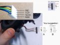
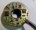
Help me identify this motors wires and how to drive them.

Thread Starter

q12x

Joined Sep 25, 2015
2,227
Hello mister @Magenta, and thank you for replying.
If you have time, watch my 2 videos from page1 of this thread:
"_Heat gun part2A - turbine transistors driver
__Heat gun part2B - turbine transistors driver (stuff I forget to mention)
"
(also give me a link to your movie or the page where you have the progress with your "led wings").
In them, I explain what I tried and how I link everything on this motor. I also explain and show the wire colors and many more.
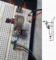
- I did indeed come across that pdf file that you show me, before as well. But I discarded it because 1-is from totally another model of the fan, and 2-the wire colors are not the same and 3-the order of the black and brown is not the same as the order of the red and black in this pdf. I also get the point with the skematic on page 7 and 8 and I tried it as well with my arduino BC139 driver system, and after that with a potentiometer (in the second movie). In short, I've already come across that pdf already, but is good that you mention it. I should have too from the start.
I connected every wire to power, the ones I thought are logically (by color) the power wires, and then the illogical ones as well. Nothing moves in either cases.
If you look on the schematic and listen from my movie I made, you will see that I tested every wire with that arrangement I did there.
As you guys think, I did think as well, the brown and black should be the power wires and they should keep the motor running at full speed , with no other wires (tach or pwm wires) connected to anything. These were the first tests I made and that is why I come to this forum to ask. Is not that I dont know how to drive a general 4 wires motor, but I dont know how to drive this particular motor, which clearly has diferent wires colors than the normal ones.
All I need from you guys is a way to further test the motor in any way possible to figure out if is indeed burned OR if it has some coded "shit" inside it. OR, if can be bypassed. If it can be run directly, bypassing all its components on its little board. But that is the last idea to try.
Thank you again !
 

Magenta

Joined May 24, 2021
21
I have watched first video and half way through second one. I have not read all the posts in this thread so may be going over old ground.

If by careful comparison of the way your turbine’s plug is wired to the standard way it is wired you have found that when you apply 0 and 12V dc to pins 1 and 2 of the plug and leave pins 3 and 4 unconnected the motor does not turn, then time to open up the fan and visually examine inside for signs of defects. Opened up you can test the components of the turbine and its circuit board.
 

Magenta

Joined May 24, 2021
21
Before you open up, could you confirm for me that you have tried connecting your 12V dc power supply directly to the power leads of the turbine and that any current limit on the power supply is turned up to provide sufficient current.
 

Thread Starter

q12x

Joined Sep 25, 2015
2,227
Here it is:
Actually you had a very good idea with powering UP the current source. I never thought of that before. Thats why I made this quick video, from curiosity as well. Yes, thank you for your support.
 

Thread Starter

q12x

Joined Sep 25, 2015
2,227
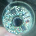
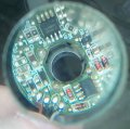
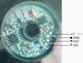
I manage to take one board out. Usually they are glued and you can not take out one while not braking the plastic case that is glued on. But this one was easy to dissassemble. So here it is:
I do not have a sckematic for it !!!! I wish i had. But maybe it is SIMILAR to other circuits you might encounter from other fans. You know? That's why Im showing it.
I will add some components values/numbers soon.
I encourage you to draw OVER image and show me what to do next. If it is a next.
20210525_151801.jpg20210525_152043.jpg20210525_152051.jpg
 
Last edited:

Thread Starter

q12x

Joined Sep 25, 2015
2,227
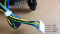
I made this little sketch for US to see it more clearly.
Until now, I only power it accordingly to it's given colors.
So you are suggesting to wire it as the other motors, like a normal/common way of wiring ?
That's an idea ! Yes.
IMG_20210525_160450 1 copy 1.jpg
 

Thread Starter

q12x

Joined Sep 25, 2015
2,227
Ok, I did your experiment !
I power it up as you suggested, and in both ways as well. Nothing moves.
I did power it again now through a transistor and still, nothing.
20210525_163934 copy 1.jpg
 

Thread Starter

q12x

Joined Sep 25, 2015
2,227
What is the writing near the solder pads the 4 wires connect to ? Near the brown it says Vin. What does it say near the other three?
Excelent catch !
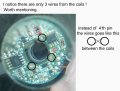
I didnt see the addnotations at all. I was concentrated on the components values only.
And I should have known this thing, that as a rule, usually, boards have inscriptions on them. I should have checked this from the start, without guessing.
So at least I was right to trust the color codes ! 1 point to me. Haha.
20210525_163934b copy 1.jpg
 

Magenta

Joined May 24, 2021
21
Please take your multimeter on low ohms range and measure resistance between:

brown and pin 5 the ground pin of FAN8413 ic - negative lead of meter on brown

black and grey wire to pin 1 the Vcc pin of FAN8413ic - positive lead of meter on black and grey

this will confirm if image A above is correct.
 
Last edited:

Thread Starter

q12x

Joined Sep 25, 2015
2,227
Please take your multimeter on low ohms range and measure resistance between:
brown and pin 5 the ground pin of FAN8413 ic - negative lead of meter on brown
black and grey wire to pin 1 the Vcc pin of FAN8413ic - positive lead of meter on black and grey
this will confirm if image A above is correct.
Updated 01
My multimeter set on 200ohm, shows nothing between brown wire and pin 5 of FAN8413 ic. (with positive probe on wire)
My multimeter set on 200ohm, shows nothing between brown wire and pin 5 of FAN8413 ic. (with negative probe on wire)

My multimeter set on 200ohm, shows nothing between b&g wire and pin 1 of FAN8413 ic. (with positive probe on wire)
By "nothing", I mean it shows 1, which is the "in air", or untouched, or un-shorted , or no resistance value.
 
Last edited:

Magenta

Joined May 24, 2021
21
And what about the other reading? Ie black and grey to pin 1 of the FAN IC. My battery is about to expire. The investigation uses the fact that on the FAN ic pin 1 is Vcc and pin 5 is ground/0V. Thus should enable you to confirm which of the four leads are Vcc and ground. Be careful with polarity of ohmmeter leads because there may be some reverse polarity protection diodes in circuit Between input power leads and circuit boards Vcc and ground tracks.
 
Last edited:

Thread Starter

q12x

Joined Sep 25, 2015
2,227
Multimeter set on 200ohm, shows nothing between b&g wire and pin 1 of FAN8413 ic. (with positive probe on wire)
All the wire tabs to pin 1 of FAN8413 ic shows nothing on multimeter.
Yes, thank you so far, we did more today than I did in 2 weeks.
Thank you for your time. This is a very complicated subject and I know it.
 

Magenta

Joined May 24, 2021
21
Could we restart on this tomorrow morning? You might want to check out the diodes on the board with your ohmmeter. I have been reading the data sheets for the two ics and can explain to you what they do.

If you have the inclination to do so, use the fact about the FAN ic pins 1 and 5 to discover which wires are 0V and Vcc.

https://www.alldatasheet.com/view_datasheet.jsp?Searchword=FAN8413

For the pwm lead you should measure a resistance in the low orders of 100k to ground. Study the pages of the turbine data sheet.

For the tacho lead with ohmmeter minus lead on ground you will measure a very high resistance; for this taco lead to Vcc you should read open circuit because this output is open collector configured. Study the pages of the turbine data sheet.

Interesting eh?
 
Last edited:

Thread Starter

q12x

Joined Sep 25, 2015
2,227
I already got through the datasheet but im not sure is the correct one since no one is simple "FAN8413" but with some letters after this name. I opened the first one in the list: FAN8413M. I hope is the same thing with what I have here. I will study it more deeply, I hope, as you suggest and check the diodes as well on the board.
We can do it anytime you want, no problems. Right now Im continuing to fit that heating element SomeHow. Ive already find a solution to stabilize it, but I wait for the composition to harden enough, before I will test high temperatures of 300 gr C on it.
 

Magenta

Joined May 24, 2021
21
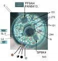
Good morning. Would you please check the six diodes I have circled in red in the attached image? Also check that the red diodes are making contact - it looks to me from the image they are pushed into a holder.

Next would you see if there is continuity ie low resistance between either end of these diodes and any of the four leads but in particular the Vcc and GND. I am not absolutely sure but a I think these diodes might be reverse supply polarity protection diodes.

Last for now on the SP8K4 ic do pins 1 and 3 have continuity to the gnd pin of the FAN ic pin 5?

Do pins 5, 6, 7 and 8 of the SP8 have continuity to the Vcc pin of the FAN ic pin 1?
 

Attachments

Top