Facebook
 Google
 GitHub
 Linkedin
Hello everyone,
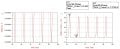
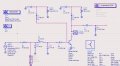
I have managed to design a Class-A amplifier at 1 GHz (see attached) using ADS
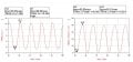
Now, I have to drive it harder to move it from class-A to class-C (From linear mode to non-linear)
I did some modifications on the circuit but I am not quite sure about the correct steps!
I have to investigate into how the resonant circuit affects the output power, and then the efficiency as a function of a conduction angle and so on.
Is there anybody can help with the right starting off steps please?
N.B: I am still new to an RF design world, so please make it simple as much as you can
Your help is much appreciated
I have managed to design a Class-A amplifier at 1 GHz (see attached) using ADS
Now, I have to drive it harder to move it from class-A to class-C (From linear mode to non-linear)
I did some modifications on the circuit but I am not quite sure about the correct steps!
I have to investigate into how the resonant circuit affects the output power, and then the efficiency as a function of a conduction angle and so on.
Is there anybody can help with the right starting off steps please?
N.B: I am still new to an RF design world, so please make it simple as much as you can
Your help is much appreciated
Attachments
-
 127.8 KB Views: 18
 -
 90.5 KB Views: 12
 -
 119.7 KB Views: 14
")