help in designing a switching circuit for amplifier circuit

Thread Starter

Preety

Joined Apr 14, 2014
41
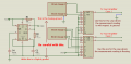
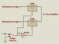
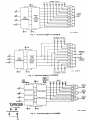
hello! i have an amplifier circuit which i need to use for two wheatstone bridge outputs. in this sense i need to design a switching circuit which will read either outputs one at a time. can anyone please help me with the design requirements (a schematic circuit for guidance is best for me right now) and some explanation regarding the time interval between the two readings? help needed please!!
 

MrCarlos

Joined Jan 2, 2010
400
Hello Preety

I think the easiest way would be to use a SPDT switch.

But if switching Of that switch affects your circuit:
Let's assume that you drive signals are low power.

You could use the IC 4066 for your design.

This IC is an electronic switch which changes state on off, through its control inputs.
If high level is closes, If low level is opened.
 

Attachments

Thread Starter

Preety

Joined Apr 14, 2014
41
thanks for the reply! i was reading through some other posts and found that i may use a 4051 IC so i already ordered for it. will it have the same function as the 4066? would you be having a schematic circuit (with resistors and other components etc)of how to implement the circuit? do i need an external clock for setting the time interval between reading from one input to the other? i apologise but my electronics is a bit poor since i am from mech eng field and i don't know how to calculate the appropriate values of all components required for the circuit but i need to use all this for my project. thanks!
 

MrCarlos

Joined Jan 2, 2010
400
Hello Preety

You say:
I was reading through some other posts and found that I may use a 4051 IC so I already ordered for it.
Will it have the same function as the 4066?

Well, yes, the 4051 will also serve for this purpose. But this has more control inputs.

You say:
Would you be having a schematic circuit (with resistors and other components etc) of how to implement the circuit?

The selection of either wheatstone bridge is automatic or manual?
If it is automatic, how long each one should be selected?
If manually, with which device would be selected?

- I have no schematic to do what you intend to do. I would have to do it.

You say:
Do I need an external clock for setting the time interval between reading from one input to the other?

If the selection is automatic, one Clock signal would be necessary, and some other components

Give Me a broader explanation of what You intend to do to help You better.
 

Attachments

Thread Starter

Preety

Joined Apr 14, 2014
41
Thanks you so much for reverting. Part of my project is to control the pitch of a two bladed wind turbine model. I have to ensure that the blade which is at highest point gets pitched by a servo to give the same strain as the blade which is at lowest point, hence subject to lowest strain. In this way the two blades deflection will be the same thus reducing load unbalance. So i need the two readings to be obtained as fast as possible, firstly measuring the lowest strain then checking the highest one and continuing this cycle for example for varying wind speeds etc. The switching must be automatic with minimum time interval between the two readings. The output of the switch must be fed to the amplifier which will then give an output to a microcontroller (using c++). The control between the servo and wheatstone bridge readings will be through programming. I hope you can help me out!
 

bertus

Joined Apr 5, 2008
22,277
Hello,

The 4051 is a 1 out of 8 selector.
You might consider a 4053 wich is a triple 1 out of 2 selector.

Here is a picture from an old RCA databook, to compare the 4051, 4052 and 4053:


Bertus
 

Attachments

Thread Starter

Preety

Joined Apr 14, 2014
41
Thanks for the reply! So i guess i just ordered the wrong component :( . i really do not understand much about all this! any good references where i can get some understanding about what i am trying to implement? Thanks!
 

MrCarlos

Joined Jan 2, 2010
400
Hi Preety

It is more complex than I thought.
I say this so that you mention in your post #5.

- Part of my project is to control the pitch of a two bladed wind turbine model.

I have to ensure that the blade which is at highest point gets pitched by a servo to give the same strain as the blade which is at lowest point, hence subject to lowest strain.

In this way the two blades deflection will be the same thus reducing load unbalance.

So I need the two readings to be obtained as fast as possible, firstly measuring the lowest strain then checking the highest one and continuing this cycle for example for varying wind speeds etc.

The switching must be automatic with minimum time interval between the two readings.

The output of the switch must be fed to the amplifier which will then give an output to a microcontroller (using c++).

The control between the servo and wheatstone bridge readings will be through programming.

I hope you can help me out -

With my best intention to help: I do not like to be guessing what someone really wants to do.

I would like to know (to see) how much have you done with your design.
The Wheatstone bridge, you have already done ?
What devices are you using for the Wheatstone bridge ?
The amplifier, you have already done ?
What microcontroller are you using?
You have already made the source code for the microcontroller?

If nothing is done but just the basic idea, it would be advisable to start by designing the Wheatstone bridge. . . Right ?

Otherwise we are wasting valuable time with messages back and forth without promptly achieve the goal.
So, let Us see (To know) what have you done with your design,

Thank you
 

Thread Starter

Preety

Joined Apr 14, 2014
41
hello again! i already have my two wheatstone bridges and the amplifier circuit. the wheatstone bridges consists of strain gauges which have already been fixed. i am using mbed microcontroller (1768NXP). i only lack the switching circuit which will allow proceed. further to that i will update my program codes. basically i have everything except the switch.
 

bertus

Joined Apr 5, 2008
22,277
Hello,

Can you provide a schematic of how the bridges should be switched to the amplifier?
I would assume a bridge has two signals the would need to be switched.

Bertus
 

Thread Starter

Preety

Joined Apr 14, 2014
41
I don't really know how it must be between the bridge and switching circuit. but below is an overview of what i want. the bridge supply voltage are at -0.6V and +0.6V. can i supply the bridge supply voltages directly to the amplifier and use only the -input and +input via the switch?
 

Attachments

Thread Starter

Preety

Joined Apr 14, 2014
41
Thanks for the pdf file but actually i already have the amplifier circuit which i bought pre-designed. the circuit has defined terminal blocks for the -BS, +BS, -IP and +IP so it is pretty easy to connect straight to the bridge. I am only worried of how to go about the switching circuit.
 

MrCarlos

Joined Jan 2, 2010
400
Hello Preety

See. . . again.

Those strain gauges, I mean:
The measurement they give is with respect to the ground ?
Or is floating measurement ?
Either way.

Now, a pulse generator is required for automatic switching.
I do not know what is the maximum frequency at which the 555 works but I think it could serve for your purposes.
The switching frequency, which you've mentioned, but did not say how much or in what range.
I am attaching a pulse generator calculated to oscillate at 300 KHz.

I hope all the documents that I'm attaching you serve
 

Attachments

Thread Starter

Preety

Joined Apr 14, 2014
41
thank you very much for your time Mr Carlos. this surely gives me some idea about the whole thing and i apologise for not having been very precise. the reading is w.r.t the ground so i will be using case 1. once again thanks very much!!
 

Thread Starter

Preety

Joined Apr 14, 2014
41
Hello again. i need some help in understanding what is happening in my MUX switching circuit which i have implemented following the advice given in the previous posts. basically the circuit works fine. i am feeding the output of the MUX to an amplifier which in turn sends the appropriate signal to a micro-controller. however, i wanted my gauge 1 to follow the same strain level as gauge 2 which i have set as the reference. i have written the codes for this application but the results are a little controversial and i am having the following problem:
I am using the 4053 MUX and the mbed processor. the MUX switching is very short time and hence i tried to read both strains at same time with my codes. however i noticed that when i do that both strain readings are already at the same value as from the beginning without the actuator doing anything (to recall it is the actuator which must adjust gauge 1 to the correct range of value). if i read the strains by calling two different functions with a very short delay in between (0.00001 s), the actuator reacts but still it does not seem that the gauge 1 is tracking gauge 2 correctly. I am worried if my codes are working properly or if it is the MUX switch and if the delay i include between calling the two functions will affect the response i am obtaining because i cannot see a good pattern in the results i am obtaining. Can anyone advise me on this please?
 

MrCarlos

Joined Jan 2, 2010
400
Hi Preety

There are several things that you should take in consideration for your design.
Strain gauge; How much time does it take to present a new reading ?
Wheatstone bridge; has a delay too ?.
The 4053 MUX; It is switching between bridge 1, bridge 2, how much time it takes to present at its output an acceptable reading ?.
The amplifier; what is the frequency response ?.
The ADC in the 1768NXP; how long it takes to make a conversion ?.

Using an oscilloscope would be easier troubleshooting the system.
What I would do first is, without feedback correction, troubleshooting from the Strain gauge to the MUX output which would controlled by the 1768NXP. with a simple code.
That way I could go see how signals flow.

When I get a good signal then connect the amplifier to verify how its output.

and so, step by step to the end. The corrective feedback, I mean, the factor you want to control.

Note that your system is a closed loop system. How much time, total, it takes to make a correction ?.
Remember the mechanical parts that must be moved.

Or where do you think you have the biggest problem ?.
 

Thread Starter

Preety

Joined Apr 14, 2014
41
Hello! well from the datasheet of the 4053 MUX i know that the switching time is around 4ns whereas the ADC clock freq is 100MHz. the switching time is less than the conversion time of the ADC so i wanted to get both readings from the strain gauges without having to include a delay in between calling the two functions because i guess that in the long run the small delay will accumulate to give a bigger one which may affect the tracking of gauge 1 to gauge 2. i tried doing it simultaneously but i observed that the two strain readings were close to each other without any action from the servo(when the readings were expected to be different). this is one of my major concern and this is making me doubt the values that i am recording for each strain gauge, although in each function i set the appropriate bits to read from each gauge. also, the amplifier that i am using is a pre-built one, how do i determine its frequency response? about the correction time i am unable to tell since i do not even see that gauge 1 is following gauge 2. the two values keep changing at all time and it is very difficult to determine what is really happening in the system.
 

Alec_t

Joined Sep 17, 2013
14,314
i observed that the two strain readings were close to each other without any action from the servo(when the readings were expected to be different)
What is the rated conversion time of the ADC (how many clock cycles)?
If your ADC has multiplexed inputs there will be a settling time before the ADC input is valid.
 

Thread Starter

Preety

Joined Apr 14, 2014
41
hi..sorry i made a mistake in my previous post. in the manual of the micro-controller it is mentioned that the ADC conversion rate is up to 1 MHz. So is there any way to proceed? do i need to include delays? if yes by how much? thank you very much!
 
Top