help in designing a switching circuit for amplifier circuit

Thread Starter

Preety

Joined Apr 14, 2014
41
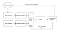
how can i know how much time the amplifier takes for the amplification of each reading? i guess when the micro-controller sends the appropriate signals to the MUX to read from gauge 1 and gauge 2 but i guess the delay occurs at the amplifier. can it happen that by the time it is processing the first signal the second one gets sent (because the switching of the MUX is very fast) and is lost? any advice on this assumption please?
 

MrCarlos

Joined Jan 2, 2010
400
Hi Preety

With an oscilloscope you could make that measurement.
Apply a signal to the input of the amplifier and an oscilloscope channel.
On the other channel of the oscilloscope you check the time it takes to get the output.

This amplifier is a homemade or You bought it, I mean, it was made by a manufacturer ?.
The data that you want to know could be in their data sheets.

By the way, the signals we've been talking about are DC or AC ?.

And as you mention at the end of your message:
in other words, it could be that the amp is over a task when you change the input signal
Yes, could be.

I have an idea:
Why not use two amplifiers and two ADC's in the microcontroller?.
That way you eliminate the switching of signals in a single amplifier.
Or are very expensive these amps ?.

You system is as seen in the attached image ?.
One thing you have not mentioned: Which device use to correct what needs to be corrected ?.


Attachments

Thread Starter

Preety

Joined Apr 14, 2014
41
hello! yes the attached drawing represents the same set-up i am using. the correction is done by adjusting the position of an RC servo motor which affects the strain gauge reading of 1. the amplifier i am using was bought from a manufacturer but no data is available regarding the amplification time taken. i do not think i have much option of buying a second amplifier though because the basic idea of the switching was to avoid buying a second amplifier. and i apologise for the confusion but we are talking only of dc signals here.
 

MrCarlos

Joined Jan 2, 2010
400
Hi Preety

Please let me know a little more about the amplifier.
Have your data sheet?.
Or the user manual?.
Model Name Manufacturing, Etc.
Scan these documents and attach them here.
I think it is necessary to know the electrical characteristics of the amplifier.

As you mention in your post #16: I am using the 4053 MUX and the mbed processor.

I would like to know how the following are connected:
1)- In the MUX 4053, what's PIN arrives wheatstone bridges 1 and 2.
2)- What code of 3 BIT's, you are applying to the MUX 4053.

You could provide that information ?.
 

Attachments

Thread Starter

Preety

Joined Apr 14, 2014
41
hi again! i am attaching the data sheet of the amplifier herewith. as for the MUX, i am using X0 Y0 for gauge 1 and X1 Y1 for gauge 2. i do not know if i did it right but i am sending A=0 and B=0 for reading gauge 1 and A=1 and B=1 for reading gauge 2. since i am not using the third input channel i have ground Z, Z0, Z1 and C. is it the right way to do it? thanks very much for your time, really appreciate!
 

Attachments

MrCarlos

Joined Jan 2, 2010
400
Hello Preety
You have a very particular way of writing.

Everything seems correct as you have it connected to the MUX and the microcontroller.
The only thing to improve is the connection of the output Z.
It is not wise to ground the outputs of the IC's, Could burn out. Is the case of the Z.

As much as you look I can not find the cause of the malfunction of your system.
It may be that the cables are very long and capture electromagnetic noise ?.
 

Attachments

Thread Starter

Preety

Joined Apr 14, 2014
41
thanks for the reply! i have used shielded cables to minimise noise. but what about the time taken by the amplifier please? apart from the method that you proposed, did you find anything of help from the data sheet? i guess that can be the problem in my opinion.
 

MrCarlos

Joined Jan 2, 2010
400
Hello Preety

No, I find nothing in the data sheets that can help us.
Now I know the strain gauge, the wheaston bridge and amplifier are the same manufacturer.
Even I found the data sheet of the amplifier. But only mentions a bandwidth of 450 KHz.
By the way: What frequency (pulse) are you applying to the inputs A & B of the MUX ?.

What kind of measuring instruments have you?
According to what you say in your message that you suspect the delay of the amplifier. Is necessary to make some measurements on the circuit to determine the delay and find out if it is what affects your system.
It could be the cause of the problem but do not know almost nothing about the amp.

Hopefully someone else give us a little light on the subject
Keep in mind what mentioned to you in Alec_t post #19.
You also have the option that bertus says in His message #12 to respect the amplifier. Of course in this case you have to stump up some cash.

If we can not make measurements in the circuit we can not move forward.
 

Attachments

Last edited:

Thread Starter

Preety

Joined Apr 14, 2014
41
Hello! Thanks very much for all the help and guidance in solving my problem. I think Alec_t was right. The ADC is the culprit.
 
Top