Help identifying a power supply

Thread Starter

CBTech_Joe

Joined Sep 9, 2020
39
Hi all,
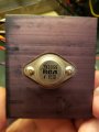
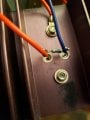
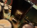
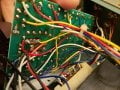
I have just picked up 3 Fischer Scientific power supplies that were in use at the local university labs. They have a variable 6V output which runs through a 6V panel meter, and they have fixed voltage points for both +/- voltages at 50, 100, 150, 250, and 500VDC. I have never seen one like this before, and it has no model number on it. I am looking to find a manual or print for these so I can know the specs and check them out properly.
20200912_171037.jpg
Any help will be appreciated.
 

Dodgydave

Joined Jun 22, 2012
11,285
Best solution is to open it up and take pics, it will probably be a multi tapped Transformer, with bridge rectifiers and a DC regulator circuit for the 0 to 6V .
Any model number?
No information on the web for me..
 
Last edited:

Thread Starter

CBTech_Joe

Joined Sep 9, 2020
39
Best solution is to open it up and take pics, it will probably be a multi tapped Transformer, with bridge rectifiers and a DC regulator circuit for the 0 to 6V .
Any model number?
No information on the web for me..
Unfortunately, there is no model number anywhere on the unit. I have searched everywhere on the web I can think of and I get nothing either. I have three of them, they are all well built and appear to be identical in construction so they were obviously mass produced. I can't believe how little information is available for them.
I will post some pictures of the inside today, but you are correct. It is a multi-tapped xfmr, a pile of capacitors, more than a few diodes, and a regulator circuit.
One odd thing is that all 3 of these units will exceed the meter range and go to 12VDC on the variable supply. I cleaned and inspected all of them before putting power to them, but they all work, voltages are very close to the labeled power, but the variables go much higher than the meter reading.
I have not loaded the supply yet so I don't know how it will perform under load.
 

Thread Starter

CBTech_Joe

Joined Sep 9, 2020
39
OK here we go.
We will start with some information about the voltages. I started with the variable 0-6VDC and compared the panel meter to the measurement of my Fluke 83. They matched up very well as you can see in the pictures below. The adjustment pot hits max meter reading at just over half of it's rotation, and at full rotation delivers around 11.51 VDC.
Next, I checked the fixed voltages with my Fluke, no load condition.
Code:
Setting       Negative to Common                  Positive to Common              Across Neg to Pos
50VDC               -58.00                              +59.88                         +118.1
100VDC              -116.5                              +188.7                         +235.6
150VDC              -175.8                              +178.2                         +354.9
250VDC              -293.8                              +297.1                         +592.6
500VDC              -579.4                              +583.8                          Did not attempt
20200913_094800.jpg20200913_094558.jpg20200913_094606.jpgI will post more pictures as I get into the unit.


moderators note : used code tags to preserve spaces
 
Last edited by a moderator:

Thread Starter

CBTech_Joe

Joined Sep 9, 2020
39
The transformer secondary reads 8.96 VAC on one half, and 9.51 VAC on the other with my household line voltage at 122.8 VAC.
 

Dodgydave

Joined Jun 22, 2012
11,285
Looks like a multi tapped transformer for the 50 to 500V DC , this will be in mA .

There is a Large heatsink at the back , must be something on that.
 
Last edited:

Thread Starter

CBTech_Joe

Joined Sep 9, 2020
39
Looks like a Jacobs Ladder for the 50 to 500V DC , this will be in mA .

There is a Large heatsink at the back , must be something on that.
Yup, there is a FET of some type mounted on the heatsink. Back side of the heatsink has a resistor across it. I will have to disassemble the rest of it to get better pictures and ID the components. There is almost no clearance between the component and the xfmr.20200913_105440.jpg
 

Dodgydave

Joined Jun 22, 2012
11,285
Ok so everything works ok then, the resistor is across the B/E terminals, do you want to modify it or just understand how it works?
 

Thread Starter

CBTech_Joe

Joined Sep 9, 2020
39
Ok so everything works ok then, the resistor is across the B/E terminals, do you want to modify it or just understand how it works?
Yes, everything works. I am looking to get a couple of things out of this. I would like to understand what it is doing and maybe build up a schematic so I know what it's capabilities are. I have 3 of them, so one may be modified to add more versatility to it as a bench supply, one left as is, and maybe one sold or donated.
 

sghioto

Joined Dec 31, 2017
5,380
The adjustment pot hits max meter reading at just over half of it's rotation, and at full rotation delivers around 11.51 VDC.
Have you tried measuring the voltage output under a load? I'm guessing at 5 amps the max output might be at around 6 volts but is it regulated or suppose to be regulated?
SG
 

Dodgydave

Joined Jun 22, 2012
11,285
Yes, everything works. I am looking to get a couple of things out of this. I would like to understand what it is doing and maybe build up a schematic so I know what it's capabilities are. I have 3 of them, so one may be modified to add more versatility to it as a bench supply, one left as is, and maybe one sold or donated.
Ok Ideally you need to make a circuit diagram of it by Reverse Engineering it, follow the wires from the transformer and do the PCB as well, it's probably a center tapped supply, bridge rectifier using two 5Amp diodes and two transistors in a Darlington pair using the 2N3055 for the 0 to 6V supply.


Here is a Possible circuit diagram for the 0-6V supply...IMG_20200913_195721_0.jpg
 
Last edited:

JoeJester

Joined Apr 26, 2005
4,390
You will find there are 10 power supply circuits for the fixed voltages. It looks like a 1N400X family of diodes (1 amp) in the half wave rectifier topology with a resistive pi filter and a bleeder resistor. In a period, long time ago, bleeders served two purposes, one was safety and the other was a minimal form of regulation. The maximum spec i found by doing the maximum calculations based on the resistors. The bleeder typically consumed 10% of the total load current for regulation.

The variable will have higher diode current to satisfy the 5A specification.
 

JoeJester

Joined Apr 26, 2005
4,390
The transformer voltages are labeled .... the 5A supply 6v - 0 - 6V.

There is a little to-220 device connected to the black tall heatsink. Is that an LM-317?
 

Thread Starter

CBTech_Joe

Joined Sep 9, 2020
39
Sorry for the delays. Real life has a habit of soaking up time I would rather spend playing.... I mean working on my electronics stuff. I have some more pictures that will hopefully clarify some of the missing information. I also placed a load on the 6V variable and the voltage does drop off when the amperage goes up. I did not pull any more than 4 amps so it wasn't loaded as fully as possible, but it dropped the voltage significantly. My circuit drawing for this will be hand drawn. I don't have any software to make the nice pretty schematics that many of you put together. I really should get something, but then I would have to spend time learning how to use another software platform. (Actually not my favorite task)

Anyway, here are more photos.
First thing of note is the voltages feeding the fixed outputs. My best translation by using both top and bottom values where the information was worn away is the following: 41V, 81V, 121V, 202V, and 400V.
I am still not sure what the current limits will be on the fixed voltages, but I am sure they will be dropping as the voltages increase. I am also not sure what the original intention of this supply is. I guess we may never know.20200915_154632.jpg20200913_173004.jpg20200915_154642.jpg
 
Top